
Spherical surface photolithography system with area differentiation

A spherical light and differential technology, applied in the field of projection exposure lithography system, can solve the problems of unsuitable for quantitative production, difficult imaging exposure, low processing efficiency, etc., and achieves convenient mask replacement, easy selection, and improved reliability. Effect

Inactive Publication Date: 2008-07-09
INST OF OPTICS & ELECTRONICS - CHINESE ACAD OF SCI
View PDF0 Cites 6 Cited by
  • Summary
  • Abstract
  • Description
  • Claims
  • Application Information

AI Technical Summary

Problems solved by technology

[0002] The traditional projection lithography technology is still plane-to-plane lithography, and it is difficult to realize the imaging exposure of the plane mask on the curved surface sample; in order to complete the exposure lithography of the plane mask on the curved surface sample at one time, a special projection objective lens system is used to correct the image. Field bending, which can only be used for samples with a specific curvature surface shape, and can’t do anything for samples with different curvature surface shapes; for current direct writing lithography, such as laser, electron beam, ion beam and other focused direct writing technologies, if equipped with a special Although the stage can meet the requirements of spherical lithography, this method belongs to point-to-point processing, the processing efficiency is extremely low, and the cost is high, so it is not suitable for quantitative production.

Method used


Image

  • Spherical surface photolithography system with area differentiation
  • Spherical surface photolithography system with area differentiation

Examples


Embodiment Construction

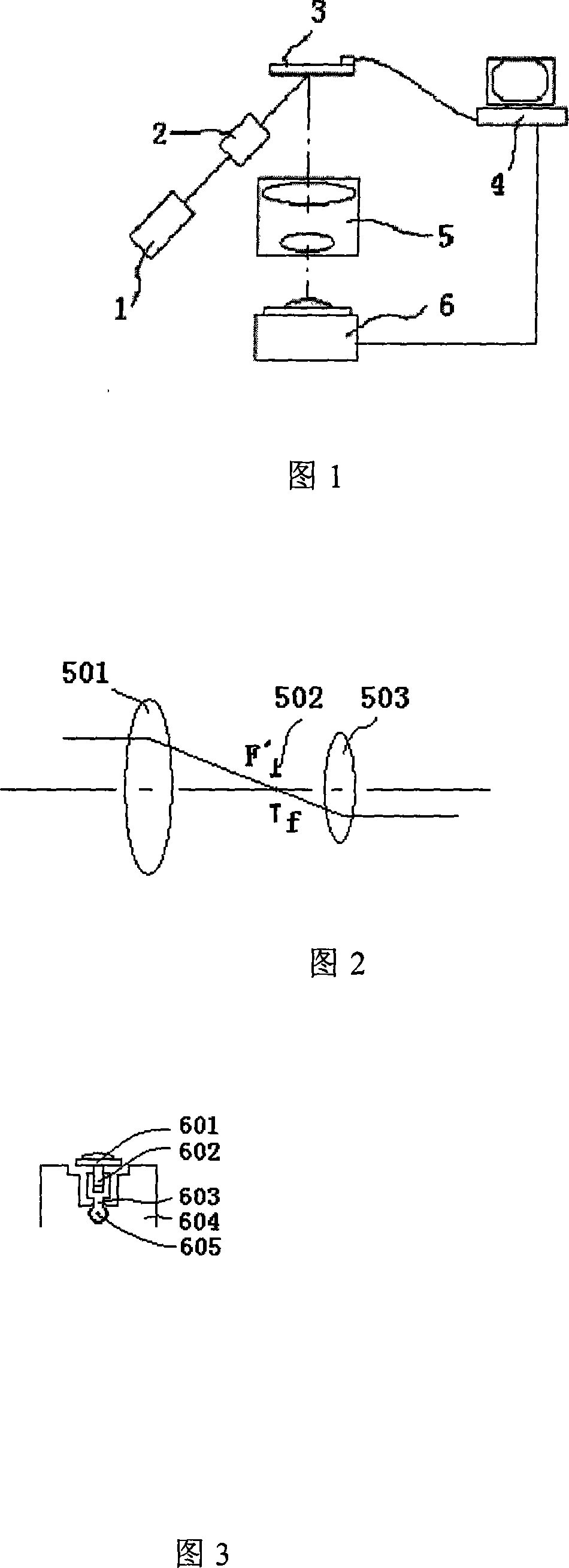
[0017] As shown in FIG. 1 , the embodiment of the present invention is composed of a light source 1 , an illumination system 2 , a mask pattern generator 3 , a computer control system 4 , a projection imaging system 5 , and an object stage 6 . The light source 1 provides the illumination light of the required exposure wavelength for the lithography system. After the illumination light is parallelized and homogenized by the illumination system 2, the mask pattern generator 3 is illuminated, and the mask pattern generator 3 is controlled by the computer control system 4 to provide a mask. At the same time, the computer control system 4 divides the exposure field according to the curvature of the sample and the focal depth of the projection imaging system 5, so that the imaging in the exposure unit is not out of focus, and the projection imaging system 5 provides the mask pattern image provided by the mask pattern generator 3 on the sample Above, the stage 6 is used to install the...


PUM


Abstract

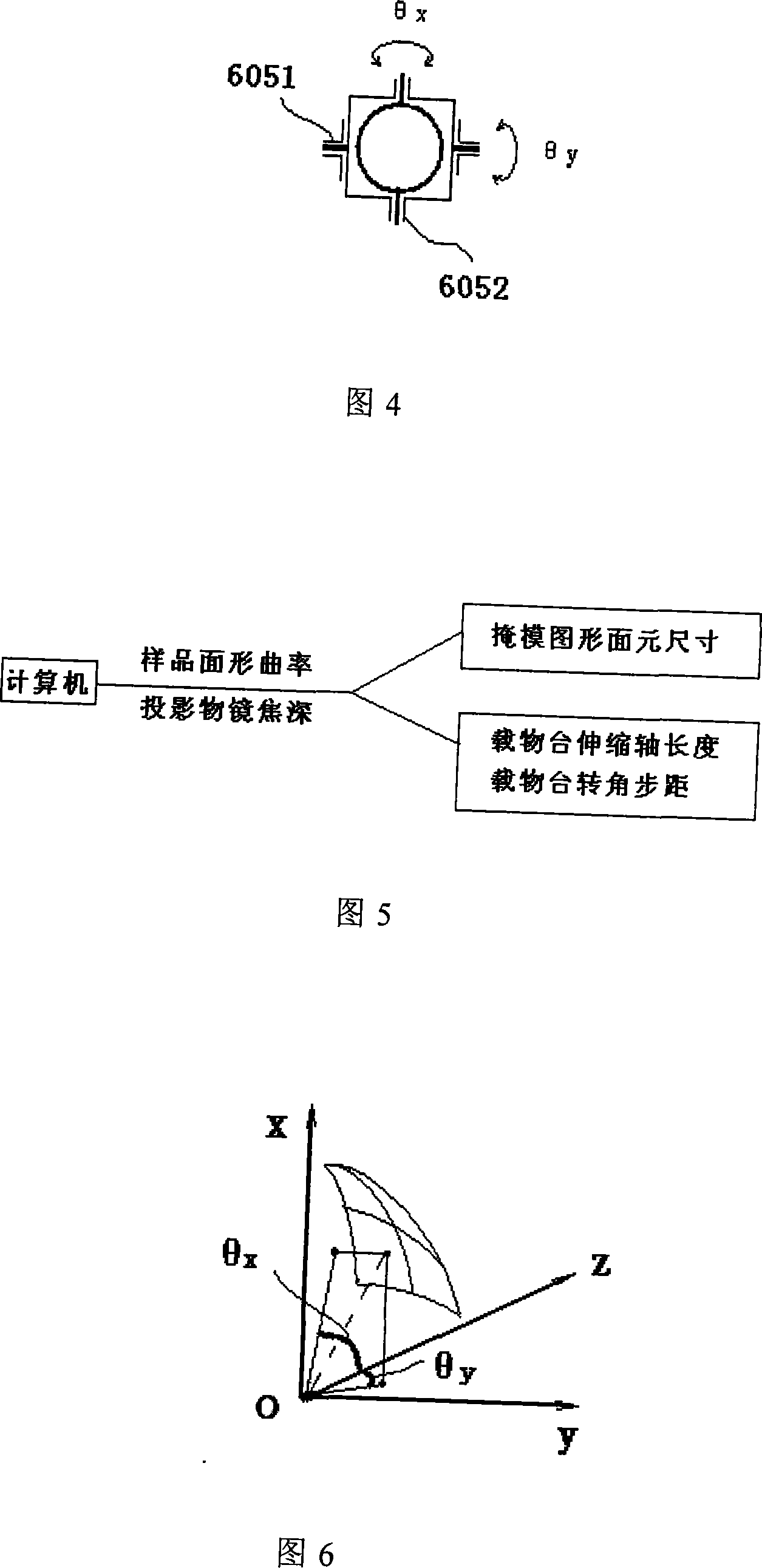
A spherical lithography system with area differentiation comprises a light source, an illumination system, a mask graph generator, a computer control system, a projection imaging system and an object table. The light source provides illumination light which illuminates the mask graph generator after being parallel uniformized by the illumination system; the computer control system controls the mask graph generator to provide mask graphs, and subdivides an exposure field into a plurality of units according to the curvature of a sample and the focus depth of the projection imaging system, so that the mask graph generator does not defocus on a single-binning imaging; the projection imaging system develops the mask graphs provided by the mask graph generator onto the sample mounted on the object table; and the computer control system identifies the swing length and the bidimensional movement of the object table according to the curvature of the spherical sample, and differentiates the area of the plane mask, thereby realizing the surface splicing lithography on the samples with different curvatures. The invention has great flexibility and maneuverability in the projection exposure lithography of the spherical samples, and has indigenous advantage in the exposure lithography of the spherical samples with different curvature radiuses.

Description

technical field [0001] The invention relates to a projection exposure photolithography system with a spherical sample, which adopts an area differential method to splicing and exposing spherical samples by surface elements to realize surface photolithography of samples with different curvatures. technical background [0002] The traditional projection lithography technology is still plane-to-plane lithography, and it is difficult to realize the imaging exposure of the plane mask on the curved surface sample; in order to complete the exposure lithography of the plane mask on the curved surface sample at one time, a special projection objective lens system is used to correct the image. Field bending, which can only be used for samples with a specific curvature surface shape, and can’t do anything for samples with different curvature surface shapes; for current direct writing lithography, such as laser, electron beam, ion beam and other focused direct writing technologies, if eq...

Claims


Application Information

Patent Timeline
Patent Type & Authority Applications(China)
IPC IPC(8): G03F7/20
Inventor 赵立新邢薇唐小萍胡松
Owner INST OF OPTICS & ELECTRONICS - CHINESE ACAD OF SCI
Learn More