
Stalk cutting test device and method

A test device and cutting device technology, which is applied in the direction of measuring device, cutting equipment, machine/structural component testing, etc., can solve the problems of difficult accurate measurement of header loss rate, increased power consumption, and difficulties in real-time signal acquisition and processing, etc. The operation method is stable and reliable, and the device is simple and reasonable.

Inactive Publication Date: 2008-07-09
JIANGSU UNIV
View PDF0 Cites 33 Cited by
  • Summary
  • Abstract
  • Description
  • Claims
  • Application Information

AI Technical Summary

Problems solved by technology

However, agricultural field experiments are affected by changes in climate, field conditions and machine parameters.
The structural parameters and motion parameters of the cutter and reeling device in the header part have a small range of changes, and it is difficult to collect and process signals in real time
The cutting performance of the cutter part is closely related to the cutting speed. The higher the cutting speed, the better the performance. With the increase of the cutting speed, the cutting resistance also decreases, but the vibration of the header increases and the power consumption increases. It is difficult to determine the law of mutual influence and the best combination of parameters
It is not easy to accurately measure the relative position change of the reel in the reeling device and the loss rate of the header under different speed ratio conditions.
There is an urgent need to design a new type of test device to solve the existing problems, but no literature related to this has been retrieved yet

Method used


Image

  • Stalk cutting test device and method
  • Stalk cutting test device and method
  • Stalk cutting test device and method

Examples


Embodiment Construction

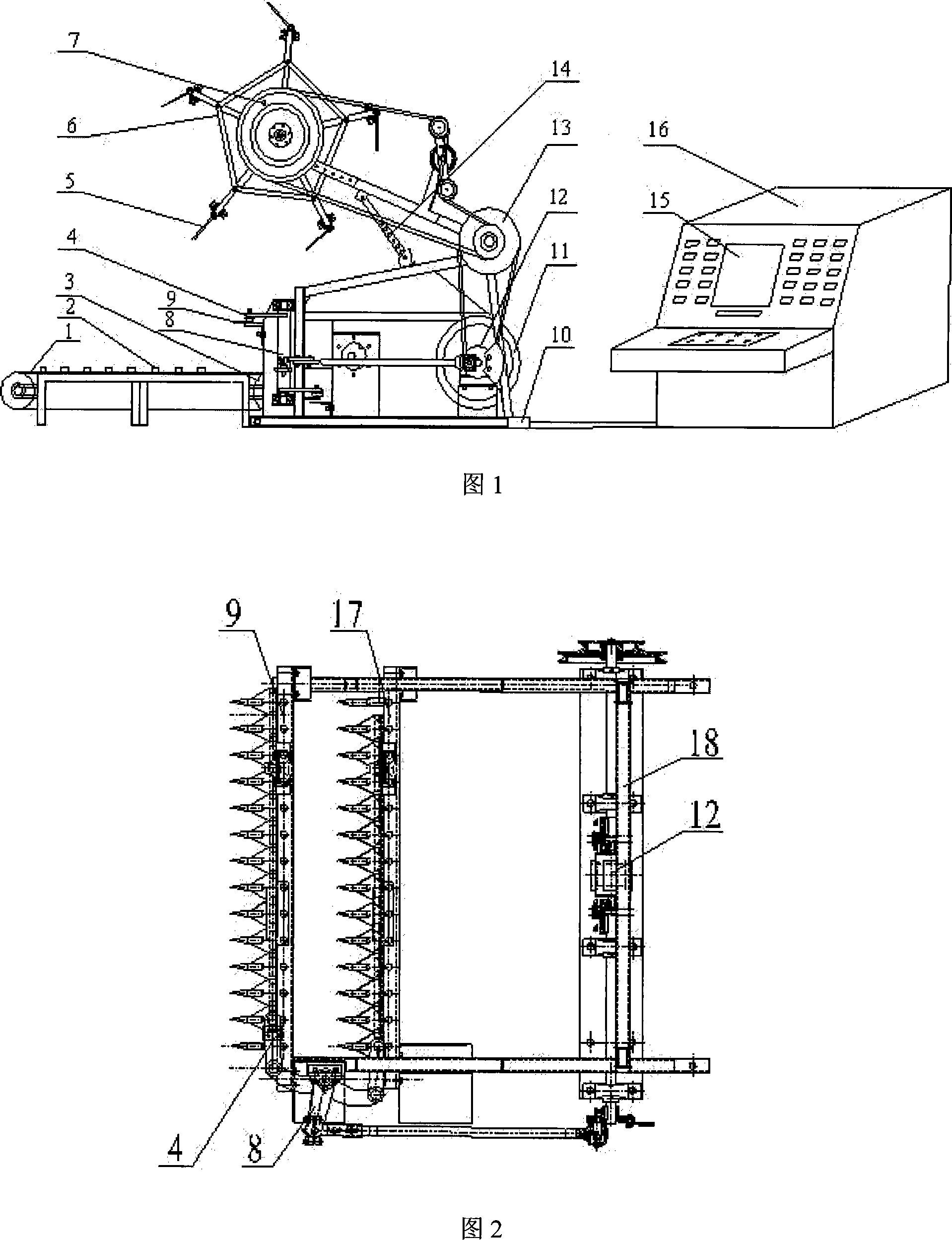
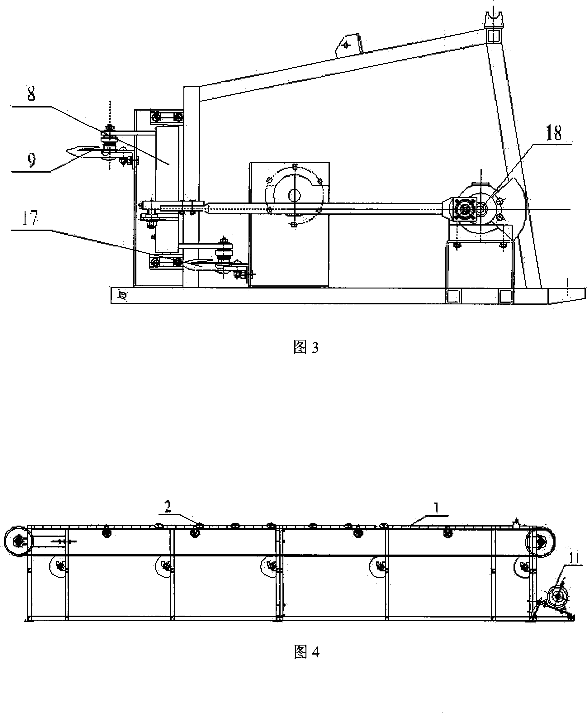
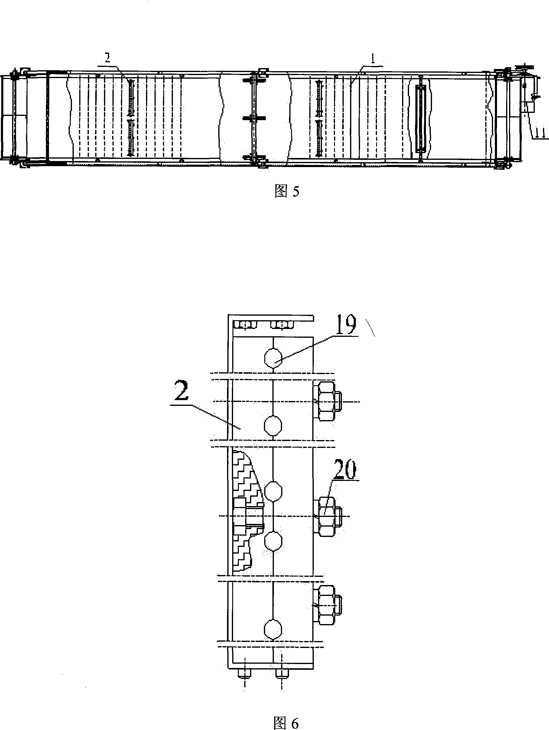
[0019] As shown in Figure 1, it is a structural diagram of the stalk cutting test device, which mainly includes a conveying device, a cutting device, a reeling device and a monitoring and control system. The conveying device includes a driving motor 11 connected to an adjustable-speed conveying belt 1 , and a rotational speed sensor 3 is installed on the shaft end of the roller of the conveying belt 1 . As shown in Figures 4, 5 and 6, the stalk holder 2 fixed on the conveyor belt 1 and capable of clamping the stalks of crops is mainly composed of stalk clamping holes 19 and clamping bolts 20, and the stalks of crops are pressed Put a certain row spacing and plant spacing into the stalk clamping hole 19, and the stalk clamper 2 is fixed on the conveyor belt 1 through the clamping bolt 20. During the test, the stalk clamp can be adjusted according to the plant spacing and row spacing of different crops. The holding device 2 can be used to meet the required plant spacing and row ...


PUM


Abstract

The invention discloses a test device for simulating indoor cutting of crop stalk and a test method thereof. The device comprises a stalk clamping device arranged on a conveying device, a grain pulling device on the stalk clamping device, a cutting device connected with a blade driving mechanism and arranged on one side of the stalk clamping device, a rotation speed sensor arranged on the drum shaft end of a conveying belt, a torque sensor arranged on a power input shaft, a pressure sensor arranged at the joint of the blade of the cutting device and a rocker connection rod. The cutting test can be conducted by collecting, recording and displaying data collected by the rotation speed sensor, the pressure sensor and the torque sensor by a test control system of a computer. The device has simple and reasonable structure and stable and reliable operation method, thus radically solving problems of the prior stalk cutting test such as parameter adjustment and realtime sampling and processing of test data.

Description

technical field [0001] The invention relates to a cutting test device for crop stalks and a test method thereof, which can be used to simulate the cutting process of rice, rape, wheat, soybean, corn, sugarcane and other crop stalks in the field indoors. Background technique [0002] At present, the research and improvement of the crop harvesting machine header part mainly includes the influence of the structural parameters and motion parameters of the cutter and the reeling device on the header. However, agricultural field experiments are affected by changes in climate, field conditions and machine parameters. The range of structural parameters and motion parameters of cutters and reeling devices in the header is small, so it is difficult to collect and process signals in real time. The cutting performance of the cutter part is closely related to the cutting speed. The higher the cutting speed, the better the performance. With the increase of the cutting speed, the cutting ...

Claims


Application Information

Patent Timeline
IPC IPC(8): G01M19/00A01F29/08A01F29/10G01M99/00
Inventor 李耀明徐立章马朝兴张立功董月亮
Owner JIANGSU UNIV
Learn More