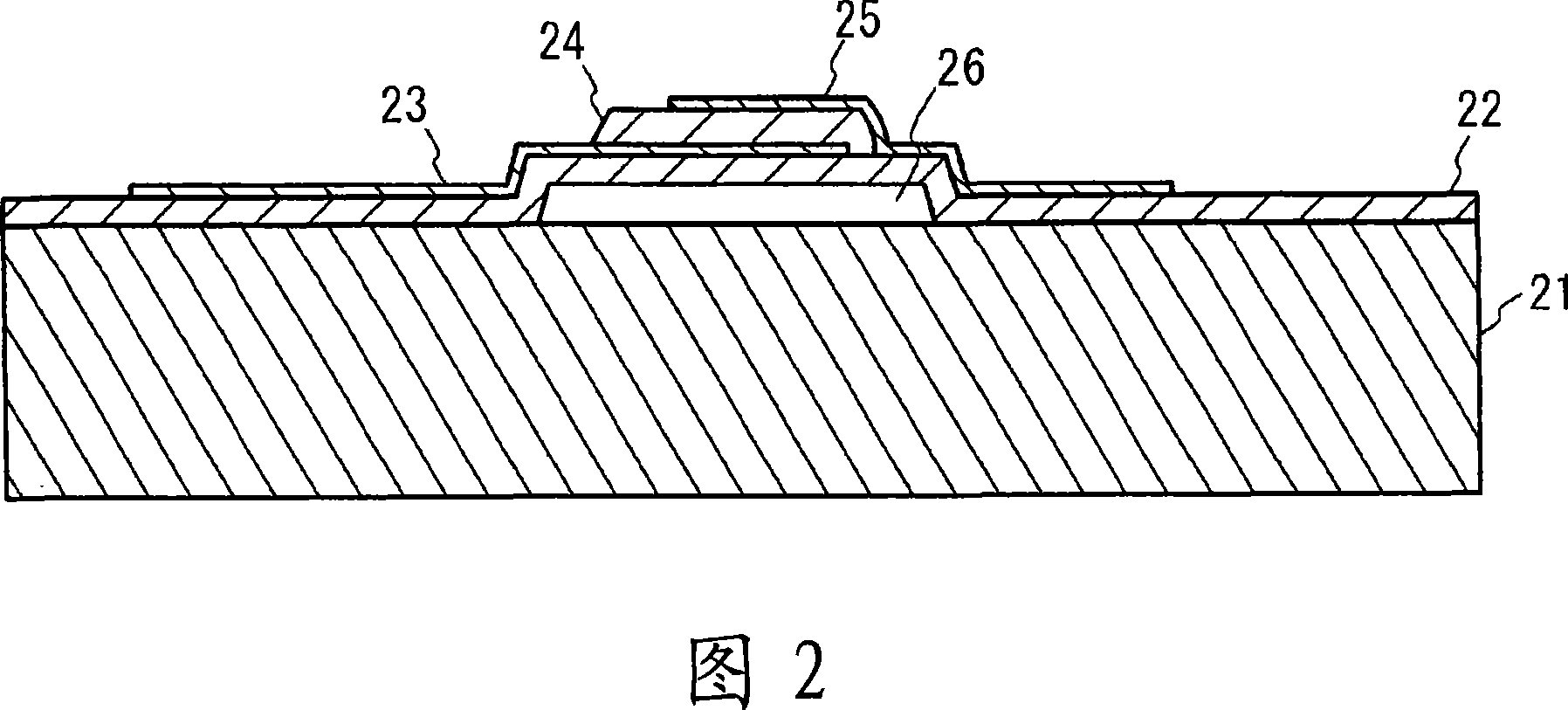
Film bulk acoustic resonator and filter
A thin-film bulk acoustic wave and resonator technology, applied in piezoelectric devices/electrostrictive devices, components of piezoelectric devices or electrostrictive devices, material selection for piezoelectric devices or electrostrictive devices, etc. , which can solve problems such as characteristic deterioration
- Summary
- Abstract
- Description
- Claims
- Application Information
AI Technical Summary
Problems solved by technology
Method used
Image
Examples
no. 1 approach
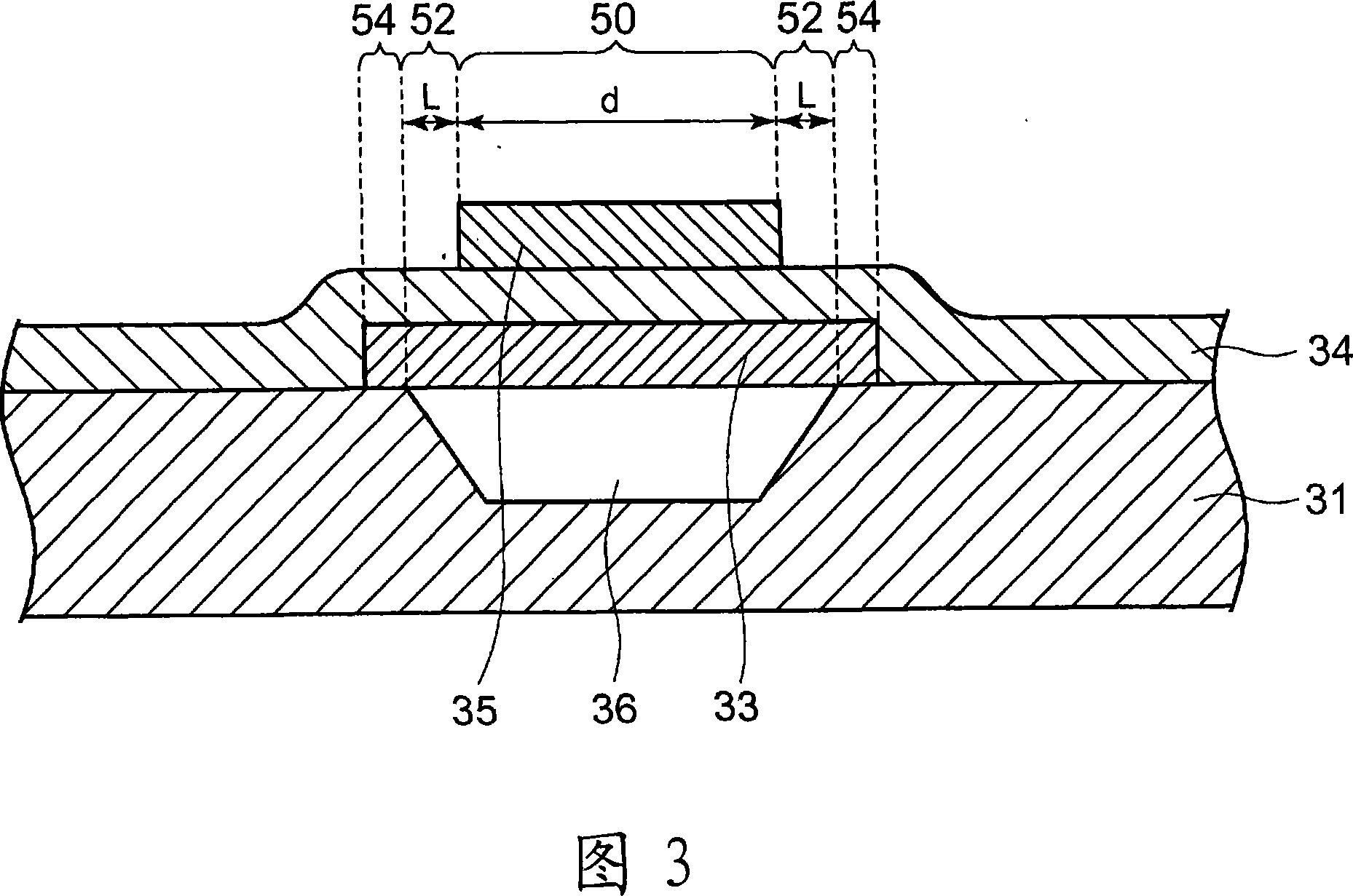
[0055] FIG. 9A illustrates a top view of the resonator according to the first embodiment. FIG. 9B illustrates a cross-sectional view taken along line A-A of FIG. 9A. FIG. 9C illustrates a cross-sectional view taken along line B-B of FIG. 9A. A cavity 46 (via hole) is formed in the Si (silicon) substrate 41 . On the substrate 41 , above the cavity 46 , a lower electrode 43 is provided. A piezoelectric thin film 44 made of AlN is provided on the lower electrode 43 . An upper electrode 45 is provided on the piezoelectric film 44 . The resonance region 50 is a region where the lower electrode 43 and the upper electrode 45 face each other across the piezoelectric film 44 . The supporting area 52 is composed of the lower electrode 43 and the piezoelectric film 44 on the cavity 46, and is arranged around the resonant area 50, except for the wiring portion 56 leading out the upper electrode 45 and its surroundings. The adjacent area 54 is composed of the substrate 41, the lower e...
no. 2 approach
[0111] Fig. 21 illustrates a schematic sectional view of a resonator according to a second embodiment. As shown in FIG. 21 , the supporting area 52 is composed of the piezoelectric film 44 and the upper electrode 45 located above the cavity 46 . The adjacent area 54 is composed of the substrate 41 , the piezoelectric film 44 and the upper electrode 45 . A cavity 46 is formed in the resonance region 50 as well as the support region 52 . The lower electrode 43 is formed in the resonance region 50 . The piezoelectric film 44 and the upper electrode 45 are formed in the resonance region 50 , the support region 52 and the adjacent region 54 . Other structures are the same as those of the first embodiment shown in FIG. 13 .
[0112]22A to 22C are diagrams illustrating calculated scattering characteristics of the resonance region 50, the support region 52, and the adjacent region 54 in the resonator according to the second embodiment. Fig. 22A corresponds to Fig. 15A. As shown i...
no. 3 approach
[0115] Fig. 23 illustrates a schematic cross-sectional view of a resonator according to a third embodiment. As shown in FIG. 23 , the supporting area 52 is composed of the lower electrode 43 and the piezoelectric film 44 located above the cavity 46 . Adjacent region 54 consists of piezoelectric film 44 over cavity 46 . The cavity 46 and the piezoelectric film 44 are formed in the resonant region 50 , the support region 52 and the adjacent region 54 . The lower electrode 43 is formed in the resonance region 50 and the support region 52 . The upper electrode 45 is formed in the resonance region 50 . Other structures are the same as those of the first embodiment shown in FIG. 13 .
[0116] 24A to 24C are diagrams showing the calculated scattering characteristics of the resonance region 50, the support region 52 and the adjacent region 54 in the resonator according to the third embodiment. Fig. 24A corresponds to Fig. 15A. As shown in FIG. 24B , in the support region 52, the ...
PUM
 Abstract
Description
Claims
Application Information
 - R&D
- Intellectual Property
- Life Sciences
- Materials
- Tech Scout
- Unparalleled Data Quality
- Higher Quality Content
- 60% Fewer Hallucinations
Browse by: Latest US Patents, China's latest patents, Technical Efficacy Thesaurus, Application Domain, Technology Topic, Popular Technical Reports.
© 2025 PatSnap. All rights reserved.Legal|Privacy policy|Modern Slavery Act Transparency Statement|Sitemap|About US| Contact US: help@patsnap.com


