
Metal member surface microscopic topographic controlled manufacturing process implement method

A technology of microscopic appearance and metal components, applied in the direction of manufacturing tools, metal processing equipment, welding equipment, etc., can solve the problems of incision blockage, difficulty in control, and low processing efficiency, and achieve improved lubrication status, increased service life, and simple process Effect

Inactive Publication Date: 2008-06-25
CHINA UNIV OF PETROLEUM (EAST CHINA)
View PDF0 Cites 13 Cited by
  • Summary
  • Abstract
  • Description
  • Claims
  • Application Information

AI Technical Summary

Problems solved by technology

The process of shot peening technology is difficult to control, and the surface morphology is not easy to control; laser texturing technology overcomes the problem that the irregular morphology of traditional shot peening technology is difficult to control, and can make the surface of the steel plate obtain controllable surface morphology, but the laser texturing technology The appearance is mainly regular distribution of "crater" morphology
However, from the perspective of tribological design, this shape is not conducive to the formation of a dynamic lubricating oil film, and the stress concentration at the edge of the "crater" shape is likely to cause cracks on the surface of the workpiece; Casting is easy to cause blockage inside the incision and the surface is rough; micro-modeling technology based on laser shock uses the force effect of laser to form micro-pit on the surface of metal components, the processing efficiency is low, and it is not suitable for the micro-morphology of high hardness and high brittle materials manufacture

Method used


Image

  • Metal member surface microscopic topographic controlled manufacturing process implement method
  • Metal member surface microscopic topographic controlled manufacturing process implement method

Examples


Embodiment Construction

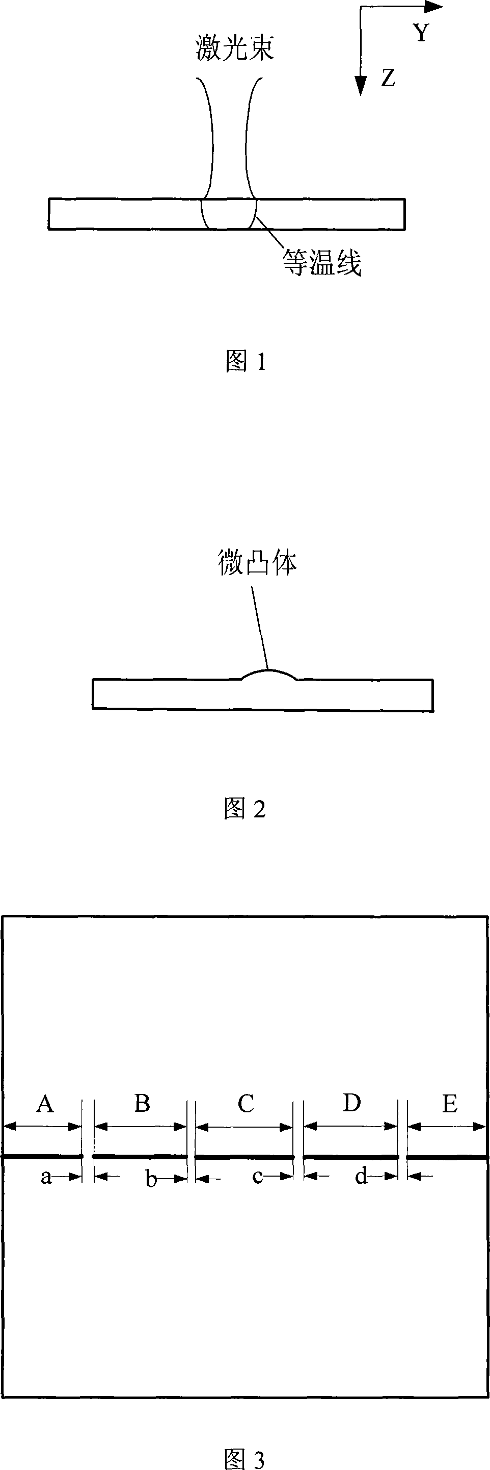
[0014] Specific embodiments of the present invention will be described below in conjunction with the accompanying drawings. The laser processing process of the surface micro-topography is shown in Figure 1. The workpiece is fixed on the worktable. The laser beam is irradiated on the surface of the workpiece with a constant power and moves along the x direction at a constant or variable speed. Natural cooling, forced convection air cooling or forced Convective water cooling cools the heated area. During the laser scanning process, the scanned part undergoes two heat exchange processes of heating and cooling in turn, and corresponding stress and deformation are generated inside it, and asperities are generated on the surface of the component, as shown in Figure 2.

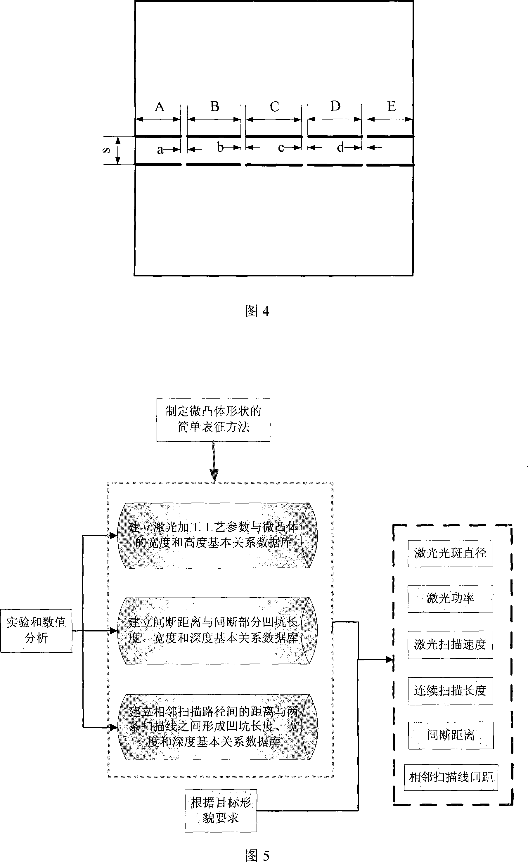
[0015] By changing the main processing parameters such as laser spot diameter, laser power and laser scanning speed, asperities of different shapes can be obtained. In order to obtain controllable surface topography...


PUM

PropertyMeasurementUnit
heightaaaaaaaaaa

Abstract

The invention relates to a method for realizing a microcosmic topography controllable manufacture on a metal component surface. The invention is characterized in that the invention realizes the processing on the microcosmic topography on the metal component surface through changing the processing technical parameters, scanning the line interruption distance as well as the length of each section of scanning line and the space between neighboring scanning routes based on that the thermal effect of laser results in uneven temperature fields on the metal component surface to lead part of the metal component surface to generate plastometric set to form a micro-bulge. The technique is characterized in that being as thermal state accumulative forming, the invention is not only suitable for a normal metal material, but also suitable for the controllable manufacture on the surfaces of high-hard brittle difficult-deforming materials like titanium alloy, nickel alloy, ceramics and silicon chip; the invention can be applied to a friction pair for bearing / gap block, cylinder sleeve / piston of different materials and has an important significance on improving the librating state of the friction pair.

Description

technical field [0001] The invention relates to a method for realizing the controllable manufacturing process of the surface microscopic topography of metal components, which belongs to the technical fields of mechanical manufacturing and friction lubrication, and can be applied to the surface topography manufacturing of various friction pairs. technical background [0002] It is estimated that about 1 / 3 to 1 / 2 of the world's energy is consumed in friction in various forms, and the materials lost by mechanical wear caused by friction are as high as tens of billions of yuan in my country every year. The friction pair is the most critical and core part of almost all mechanical products. Its tribological behavior not only affects the working performance and operating efficiency of the mechanical system, but is even the main cause of its failure. Minimizing friction reduction is a long-term pursuit of people, so the development and popularization of friction reduction technology...

Claims


Application Information

Patent Timeline
Patent Type & Authority Applications(China)
IPC IPC(8): B23K26/00
Inventor 石永军刘衍聪李传秀
Owner CHINA UNIV OF PETROLEUM (EAST CHINA)
Learn More