Optical fiber panel display assembly

A technology of optical fiber panels and display components, applied in the direction of bundled optical fibers, optics, instruments, etc., can solve the problems of complex optical path design, large optical structure size, image deformation and image quality loss, etc., to achieve simple image processing and reduce processing costs. Effects of cost and difficulty of simplification

Inactive Publication Date: 2008-06-18
黄峰彪 +1
View PDF0 Cites 5 Cited by
  • Summary
  • Abstract
  • Description
  • Claims
  • Application Information

AI Technical Summary

Problems solved by technology

[0003] For the existing optical design mentioned above, the magnification of a single lens cannot meet the application requirements, and in the optical design that requires two or more magnifications, there are image distortion and image quality loss, and the size of the optical structure is large, For the problem of complex optical path design, the same input image needs to be transformed by the optical system to obtain multiple required output images according to the design purpose. Difficult Fiber Optic Panel Display Components

Method used


Image

  • Optical fiber panel display assembly
  • Optical fiber panel display assembly
  • Optical fiber panel display assembly

Examples


Embodiment Construction

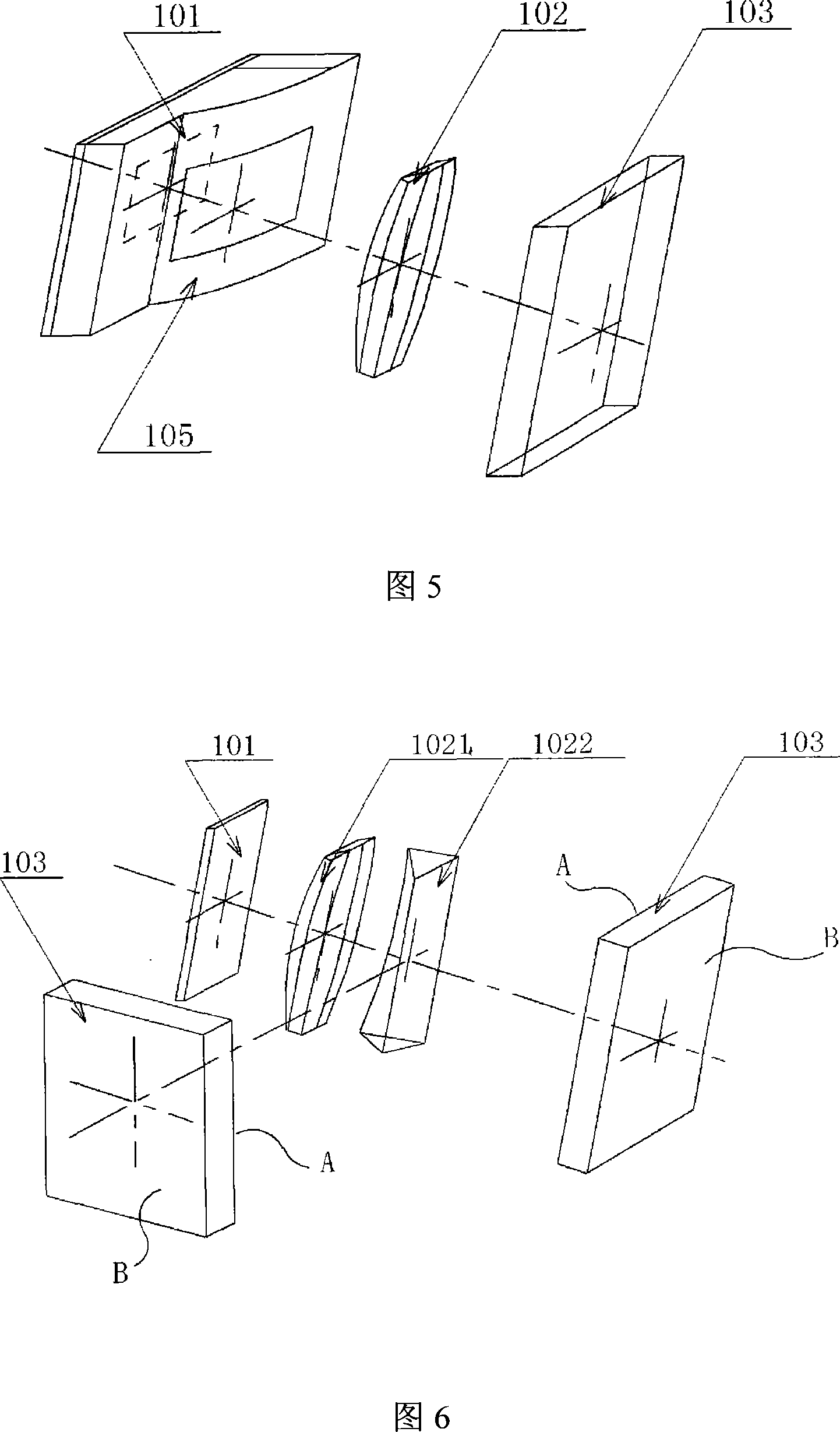
[0036] The basic structure of the optical fiber panel display assembly of the present invention is an image projection source, optical lenses, imaging optical fiber panel and connectors.

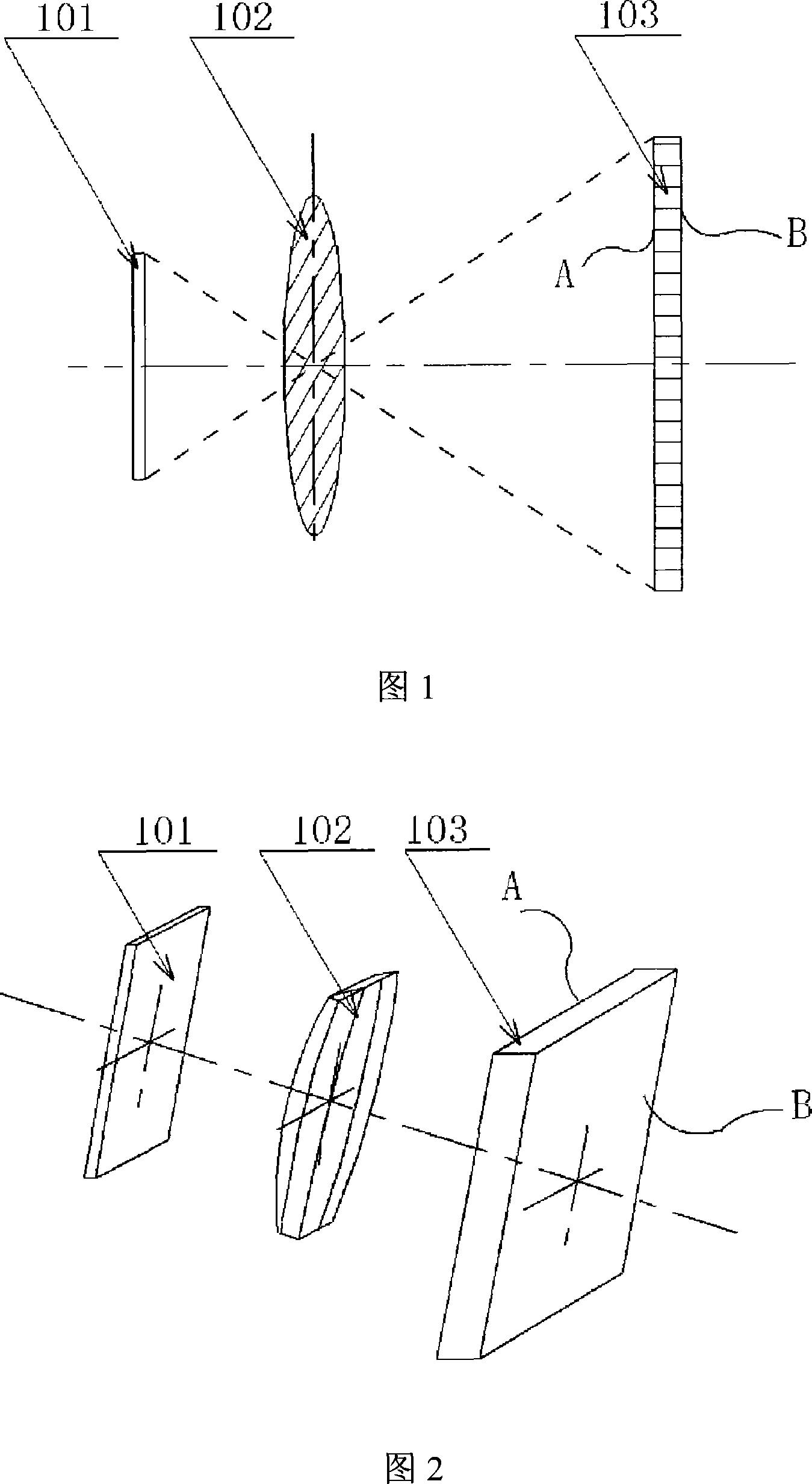
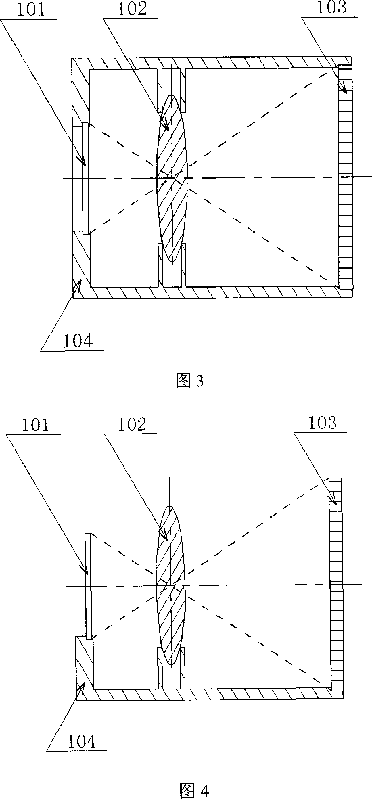
[0037] Referring to accompanying drawing 1, Fig. 1 is the implementation schematic diagram of the specific embodiment of the present invention. The image projection source 101, the optical lens 102, and the imaging fiber optic panel 103 are on the same imaging optical path axis, the image projection source 101 is on one side of the optical lens 102, and the distance between the image projection source 101 and the optical lens 102 is greater than or equal to 1 times the focal length, The imaging fiber optic panel 103 is on the other side of the optical lens 102, and the distance between the imaging fiber optic panel 103 and the optical system 102 is greater than, equal to, or less than 1 times the focal length, and its position is determined according to the design requirements of imaging. Acc...


PUM


Abstract

The invention provides an optical fiber display component and comprises an image projection source (101), an optical lens (102), an imaging optical fiber panel (103) and a connecting piece (104); in the same imaging light path axis, the image projection source (1) is arranged on one side of the optical lens (102) and the distance between the imaging projection source (101) and the optical lens (102) is equal or greater than one time focus; the imaging optical fiber panel (103) is arranged on the other side of the optical lens (102) and the distance between the imaging optical fiber panel (103) and the optical system (102) is greater than or equal or less than one time focus. The invention solves the difficult problem that image deformation and great loss of image quality may occur in two times or multiple enlargement, moreover, the invention also solves the problem that the optical structure has larger size and the design of light path is complex; the invention solves the problem that after the same inputted image is converted through the optical system, the required outputted image can be achieved according to the purpose of design; therefore, the subsequent image process becomes simple and the whole processing cost of the image is reduced.

Description

technical field [0001] The invention discloses an optical fiber panel display component belonging to the field of optomechanical integration, in particular to a device for displaying images. The device can enlarge, reduce or deform the input original image through the principle of optical projection inside the device to generate The new one or more display images are presented on multiple output surfaces for use by subsequent image processing systems. Background technique [0002] As we all know, the images produced by general display devices can be observed directly by human eyes or through some optical systems. In order to meet the needs of the human eye to observe large images, a very complex optical path design has to be adopted, which is costly and the size of the optical system is relatively large, especially when the single-lens magnification cannot meet the application requirements, and two or more magnifications are required In the optical design, the image plane p...

Claims


Application Information

Patent Timeline
Patent Type & Authority Applications(China)
IPC IPC(8): G03B21/00G02B6/06G09F9/30G09F9/00
CPCG02B6/08G03B21/00G02B6/06G03B21/005
Inventor 黄峰彪
Owner 黄峰彪
Why Eureka
Try Eureka