


Quick Research
Generate reliable direction feasibility study reports for your R&D in just a few steps.

Technical Q&A
Discover and master advanced knowledge NOW. Basics, ideas, possibilities, all at once.

Find Solutions
As an expert in R&D theories, this can generate solutions to your technical problems instantly.

Evaluate Feasibility
Analyze your overall solution with one click, know your potential R&D risks in advance.

Monitor Landscape
Get weekly tech updates, stay abreast of the latest tech innovations and key insights.
Clock synchronization device and method
A clock synchronization and clock technology, which is applied in the field of network communication, can solve problems such as unstable operation of the subsequent circuit system, influence of the subsequent circuit, and uncertain clock phase.
- Summary
- Abstract
- Description
- Claims
- Application Information
AI Technical Summary
Problems solved by technology
Method used
Image

Examples
Embodiment 1
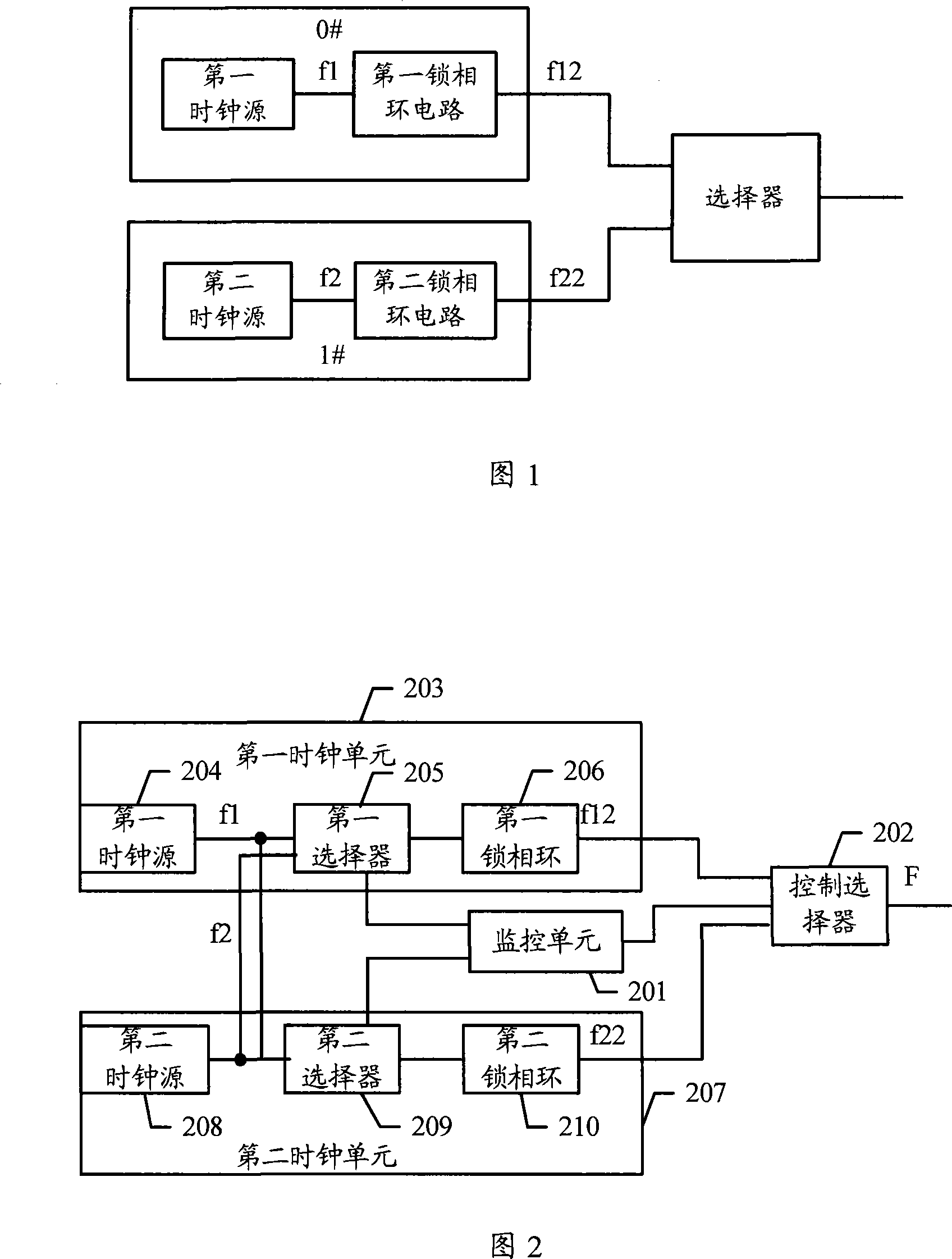
[0018] Embodiment 1. A device for clock synchronization. As can be seen from FIG. 2 , the device includes a monitoring unit 201 , a control selector 202 , a first clock unit 203 and a second clock unit 207 .
[0019] Wherein, the monitoring unit 201 is used to monitor whether the master clock fails, and the master clock may be implemented by the first clock unit 203 or the second clock unit 207 . For example, if the first clock unit 203 is used in normal operation, then the first clock unit 203 is the master clock, and the second clock unit 207 is the backup clock, and vice versa.
[0020] Wherein, the control selector 202 is used to select the standby clock as the main clock according to the result of the monitoring unit 201, and the clock provides clock input for the subsequent circuit. For example, if the first clock unit 203 serving as the master clock fails, the second clock unit 207 will be selected as the master clock. Generally, the output frequency of the first clock...
Embodiment 2
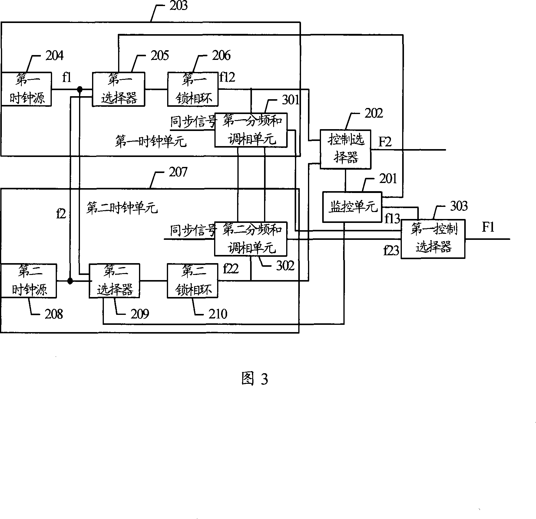
[0034] Embodiment 2, a device for clock synchronization. It can be seen from FIG. 3 that the device is similar to FIG. In the second clock unit, a second frequency division and phase modulation unit 302 is added, and a first control selector 303 is also added.
[0035] Wherein, the first frequency division and phase modulation unit 301 is used to divide the output signal of the first phase-locked loop 206, and receive the synchronization signal and the frequency division signal output by the second frequency division and phase modulation unit 302, if the second frequency division and phase modulation unit 302 is selected A clock unit 203 is used as the main clock, assuming that the frequency of the output signal of the first frequency division and phase modulation unit 301 is f13, f13 is obtained by frequency division of f12, and the phase is determined by the synchronization signal of the first frequency division and phase modulation unit 301, usually The signal obtained by f...
Embodiment 3
[0042] Embodiment 3, a method for clock synchronization, specifically comprising the following steps:
[0043] A same clock signal is selected for the first clock and the second clock, and the clock signal may be a clock signal generated by a clock source of the first clock or the second clock.
[0044] The first clock and the second clock respectively smooth the phase transitions generated by the selected clock signals, so that the output signals of the first clock and the second clock are synchronized.
[0045] Optionally, the method further includes:
[0046] The first clock or the second clock as the main clock is monitored, and when the main clock fails, the second clock or the first clock as the backup clock is selected to provide clock input for the subsequent circuit.
[0047] In addition, those of ordinary skill in the art can understand that all or part of the steps in the method of the above-mentioned embodiments can be completed by instructing related hardware thr...
PUM
 Abstract
Description
Claims
Application Information
 - R&D Engineer
- R&D Manager
- IP Professional
- Industry Leading Data Capabilities
- Powerful AI technology
- Patent DNA Extraction
Browse by: Latest US Patents, China's latest patents, Technical Efficacy Thesaurus, Application Domain, Technology Topic, Popular Technical Reports.
© 2024 PatSnap. All rights reserved.Legal|Privacy policy|Modern Slavery Act Transparency Statement|Sitemap|About US| Contact US: help@patsnap.com