Photovoltaic roof tile system

A photovoltaic and photovoltaic cell technology, applied in the field of systems, can solve the problems of reducing the efficiency of photovoltaic roof systems, loss of net collected energy, etc.

Inactive Publication Date: 2008-06-04
GENERAL ELECTRIC CO
View PDF1 Cites 5 Cited by
  • Summary
  • Abstract
  • Description
  • Claims
  • Application Information

AI Technical Summary

Problems solved by technology

However, it is often observed that a considerable amount of light escapes from the fluorescent collector and is not directed onto the photovoltaic cell, resulting in a loss of net harvested energy
This reduces the efficiency of photovoltaic roof systems

Method used


Image

  • Photovoltaic roof tile system
  • Photovoltaic roof tile system
  • Photovoltaic roof tile system

Examples


Embodiment Construction

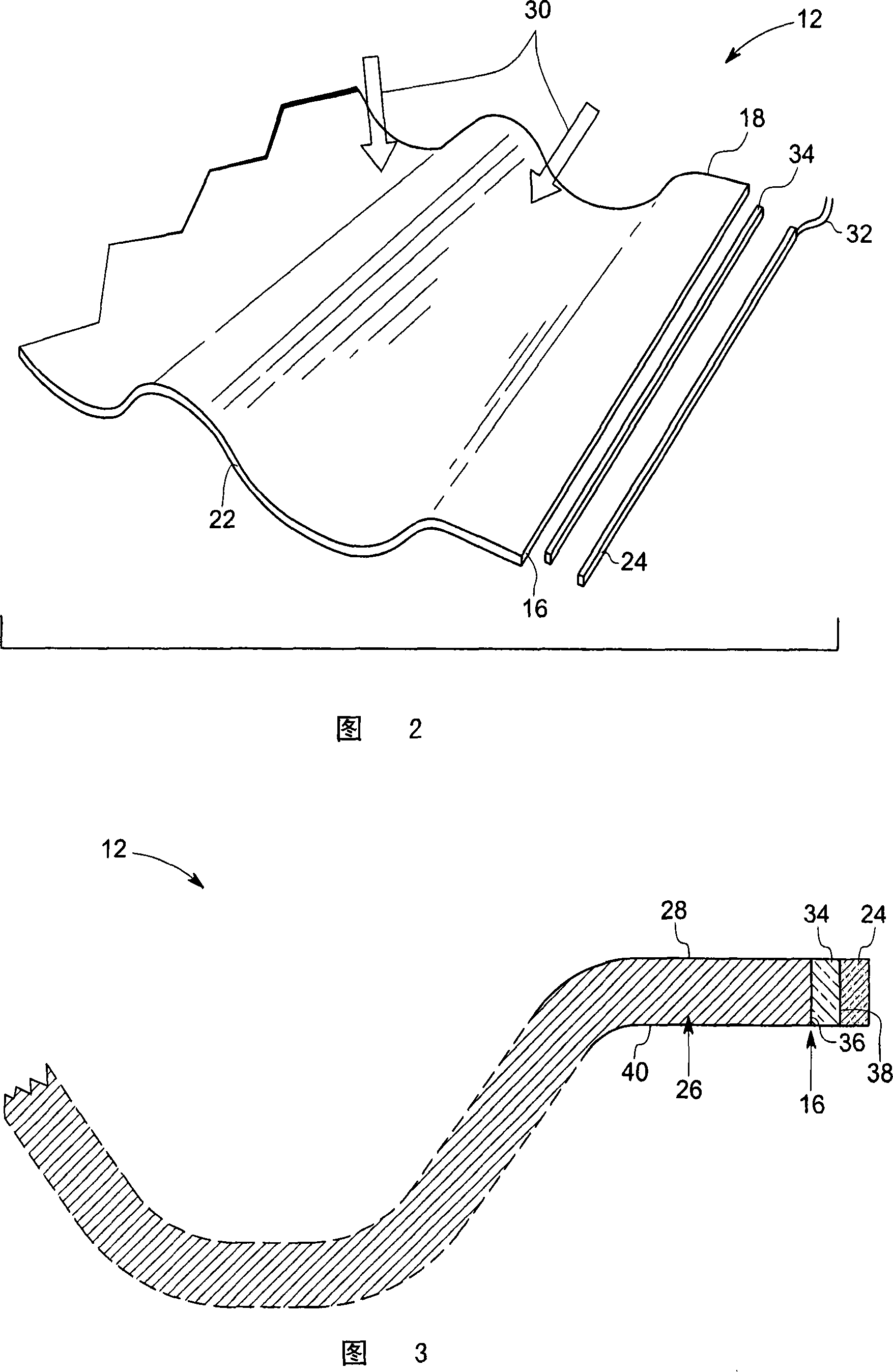
[0017] As described in detail below, embodiments of the present invention provide a photovoltaic roof tile system and a method of assembling the photovoltaic roof tile system. The photovoltaic roof tile system includes at least one photovoltaic cell attached to a fluorescent collector located on the roof tile. Embodiments of the invention disclose various modes of attaching photovoltaic cells to roof tiles. As used herein, a "fluorescence collector" includes a substrate and at least one particle having an absorption spectrum that absorbs light from multiple directions dispersed in the substrate. In one example, the absorption spectrum can include over one hundred nanometers. Absorbed light is typically emitted from the at least one particle to at least one edge of the fluorescence collector. Further details of suitable fluorescent collectors can be found in publication No. 19, 2004 entitled "Elements for roofs and building facades with photovoltaic roof tile structures with ...


PUM


Abstract

A solar tile system is disclosed. The solar tile system includes a fluorescence collector having multiple edges and configured to receive light through a face and configured to direct light towards the edges by total internal reflectance. The system also includes a photovoltaic cell coupled to at least one of the edges and configured to receive the light and convert the light to electrical power. The system further includes an optically matched interface layer disposed between the fluorescence collector and the photovoltaic cell at the at least one edge.

Description

technical field [0001] The present invention generally relates to photovoltaic cells or solar cells, and more particularly, the present invention relates to a system for integrating photovoltaic cells within architectural elements such as roof tiles and building facade elements. Background technique [0002] Photovoltaic energy is gradually becoming an important source of electricity. In addition to the use of stand-alone photovoltaic generators, the roofs of residential and commercial buildings are also well suited for photovoltaic installations. In order for photovoltaic installations on roofs to be widely accepted and utilized, they must meet aesthetic requirements and thus must be integrated with conventional roofs in appearance and configuration. In addition, they must meet all the requirements of conventional roofing materials, including weathertightness, resistance to the expected local climatic conditions and compliance with local codes and practices. In addition t...

Claims


Application Information

Patent Timeline
Patent Type & Authority Applications(China)
IPC IPC(8): H01L31/052H01L31/048E04D13/18E04D1/30F24S23/00
CPCY02B10/20Y02E10/40H01L31/0483Y02E10/52F24J2/065F24J2/0455Y02B10/12H01L31/055F24S20/69F24S23/11H02S20/25Y02B10/10
Inventor O·G·迈尔M·A·策特尔J·斯特罗姆伯格O·S·贡扎莱斯
Owner GENERAL ELECTRIC CO
Why Eureka
Try Eureka