
Multi-speed interconnected reliability testing structure

一种测试结构、互连结构的技术,应用在半导体/固态器件测试/测量、电气元件、电固体器件等方向,能够解决影响芯片功能、电路短路等问题

Inactive Publication Date: 2008-06-04
SEMICON MFG INT (SHANGHAI) CORP +1
View PDF0 Cites 14 Cited by
  • Summary
  • Abstract
  • Description
  • Claims
  • Application Information

AI Technical Summary

Problems solved by technology

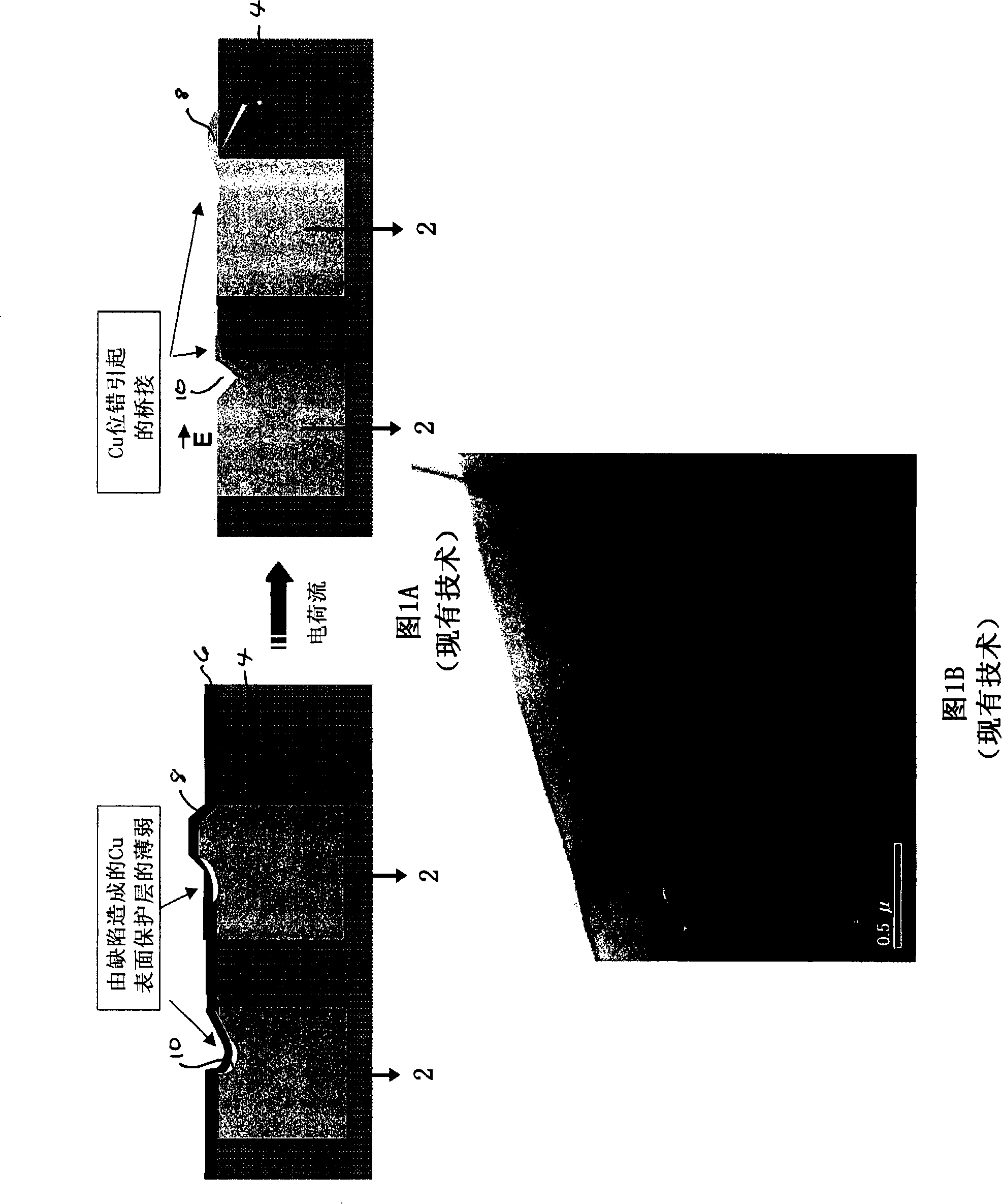
This migration can cause short circuits and also affect chip functionality

Method used


Image

  • Multi-speed interconnected reliability testing structure
  • Multi-speed interconnected reliability testing structure
  • Multi-speed interconnected reliability testing structure

Examples


Embodiment Construction

[0030] Typically, testing of metallized interconnect structures involves the investigation of different failure mechanisms. For example, the point of failure may be near the top or bottom of a via connecting different metal lines, or it may be along the metal line itself.

[0031] The entire content of the following document is hereby incorporated by reference: EIA / JEDEC Standard EIA / JESD61 (April 1997) entitled "Isothermal Electromigration Test Procedure". This document describes standardized tests for estimating electromigration (EM) along metallized feature lines of interconnect structures. In particular, the test describes a standardized test for estimating electromigration (EM) along metallized feature lines of an interconnect structure. In particular, the test is used to identify electromigration that occurs along relatively long metal lines, eg, pieces of 200 μm or greater, and typically 800 μm or greater in length. The EM test is performed by applying a loading volta...


PUM


Abstract

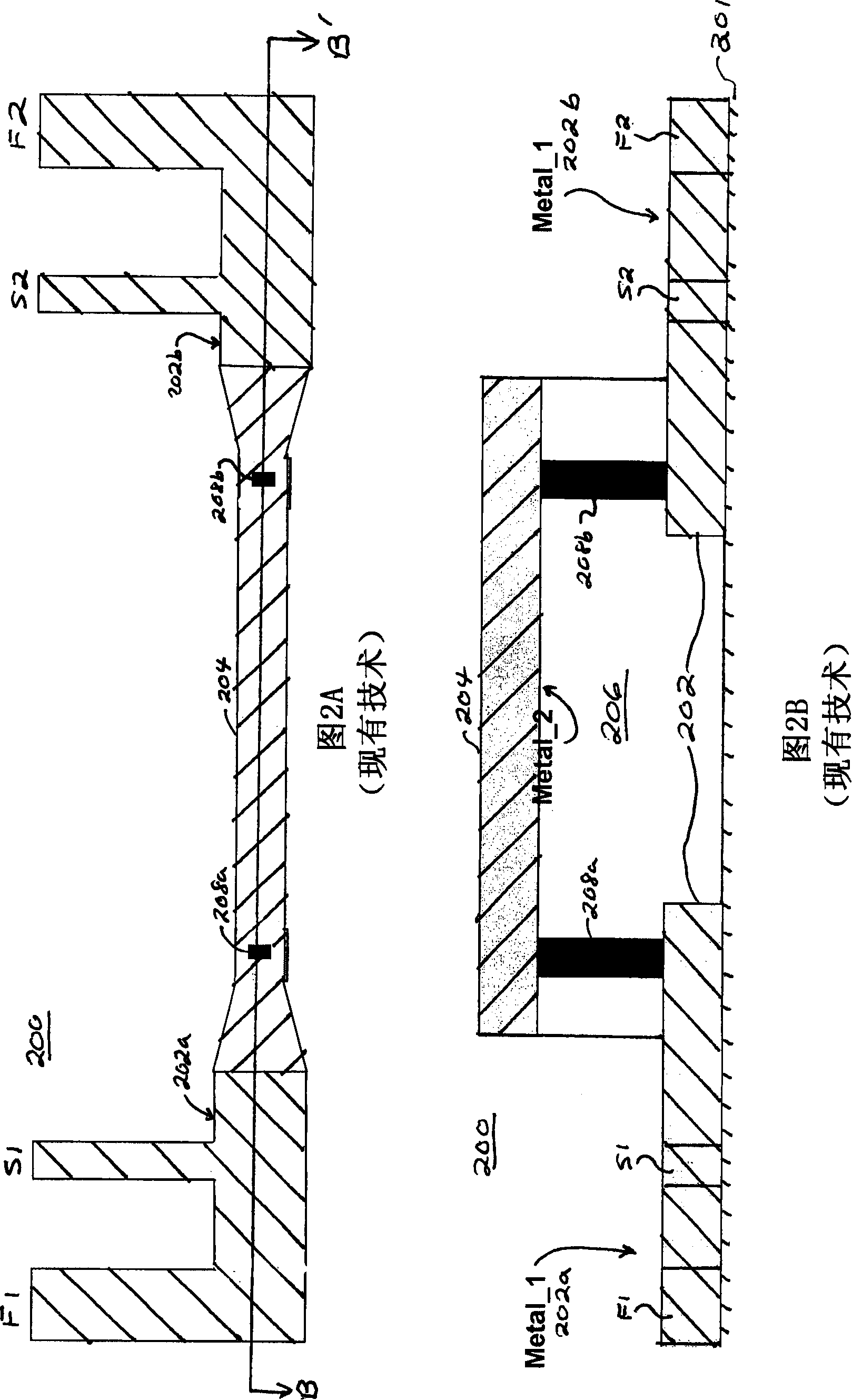
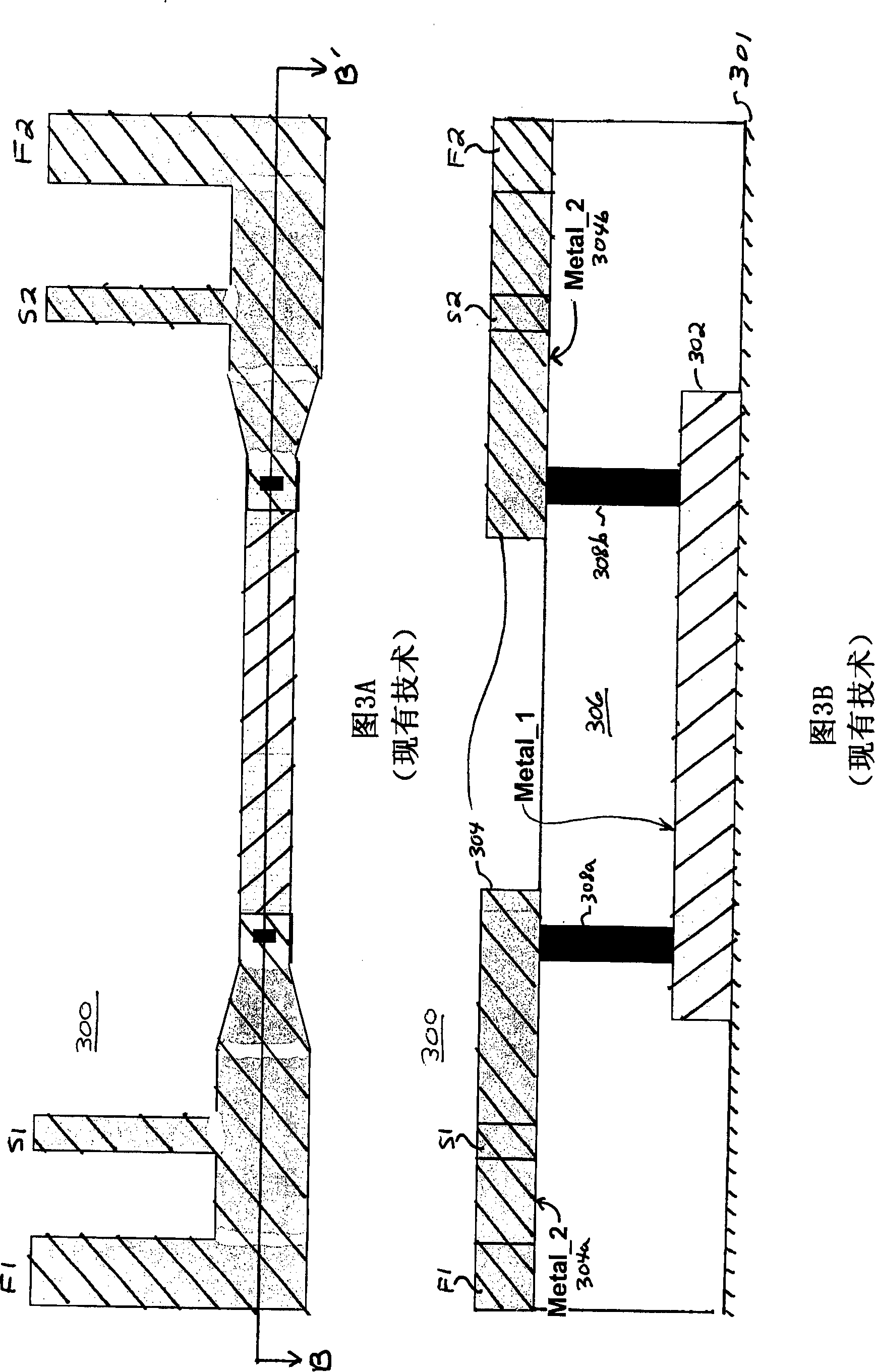
The embodiment of the invention relates to a method and structure for testing the electromigration effect in a plurality of interconnected metal layers. The embodiment of the testing structure disclosed in the invention comprises at least two sections of a different metal layer which passes the testing structure. Each section includes nodes equipped for loading and testing a voltage, and these nodes are imposed a voltage or sensed a voltage selectively, and thereby the electromigration effect in every metal layers can be detected rapidly and accurately.

Description

technical field [0001] The present invention relates to an integrated circuit and a process for the manufacture of semiconductor devices. In particular, the present invention relates to a method and system for testing the degree of integration of multilevel interconnect structures. More specifically, the present invention provides a method and apparatus for testing conductive breakdown of interconnect structures caused by electromigration, but it should be understood that the present invention has broader applications. Background technique [0002] Integrated circuits have grown from a handful of interconnected devices fabricated on a single chip of silicon to millions of devices. Today's integrated circuits offer performance and complexity far beyond what was originally imagined. To achieve increases in complexity and circuit density (ie, the number of devices that can be packed into a given chip area), the minimum device feature size, also referred to as device "geometry...

Claims


Application Information

Patent Timeline
Patent Type & Authority Applications(China)
IPC IPC(8): H01L23/544H01L23/522H01L21/00H01L21/768H01L21/66
CPCH01L22/34H01L2924/0002H01L2924/00
Inventor 施雯阮玮玮
Owner SEMICON MFG INT (SHANGHAI) CORP
Learn More