


Quick Research
Generate reliable direction feasibility study reports for your R&D in just a few steps.

Technical Q&A
Discover and master advanced knowledge NOW. Basics, ideas, possibilities, all at once.

Find Solutions
As an expert in R&D theories, this can generate solutions to your technical problems instantly.

Evaluate Feasibility
Analyze your overall solution with one click, know your potential R&D risks in advance.

Monitor Landscape
Get weekly tech updates, stay abreast of the latest tech innovations and key insights.
Capteur de pression a clapet anti-retour
A pressure sensor and check valve technology, applied in the measurement of fluid pressure, instruments, brakes, etc., can solve the problems of high assembly, high production cost, high structural space requirements, etc., to reduce the number of components, reduce assembly costs, and reduce The effect of structural space
- Summary
- Abstract
- Description
- Claims
- Application Information
AI Technical Summary
Problems solved by technology
Method used
Image


Examples
Embodiment Construction
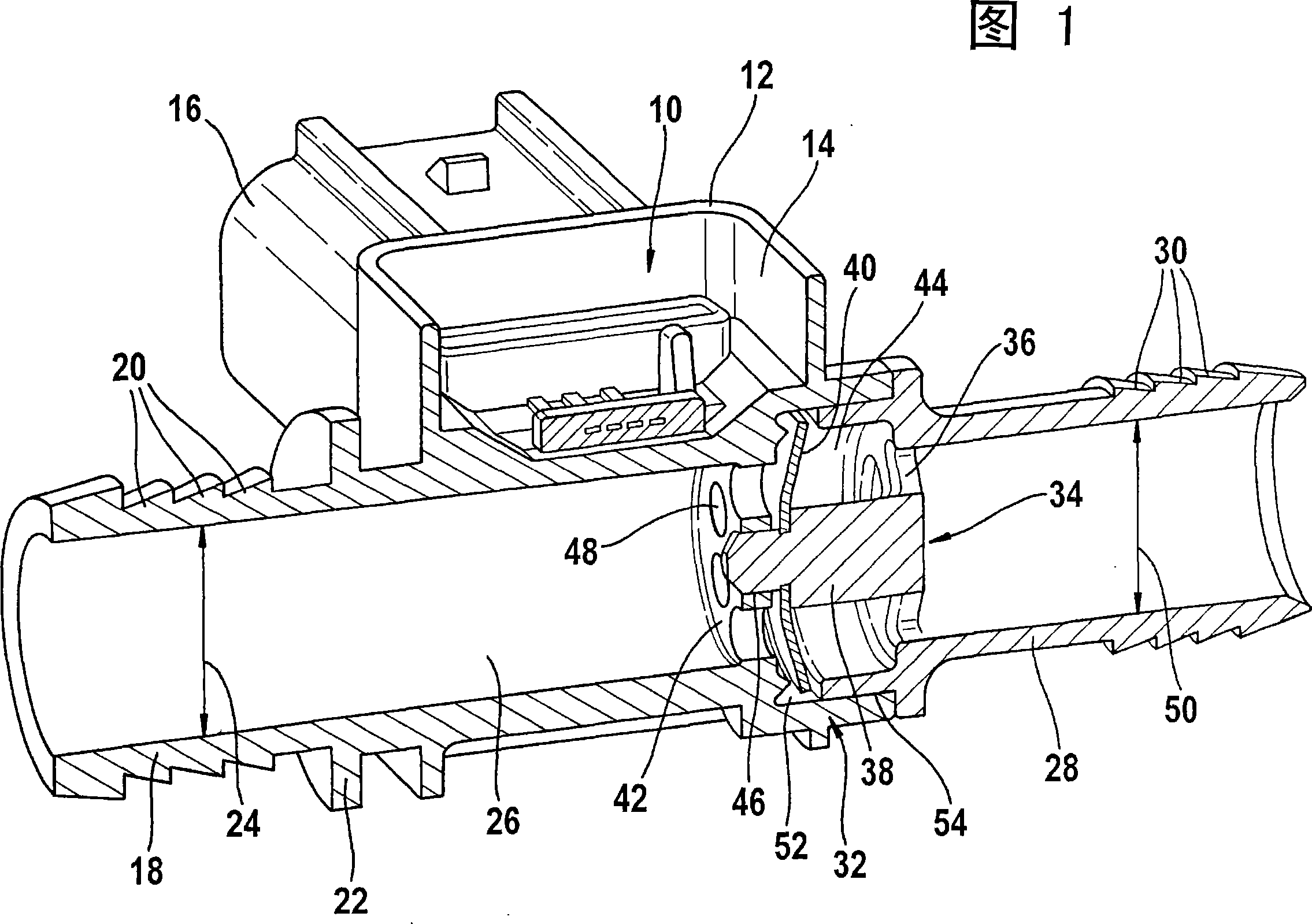
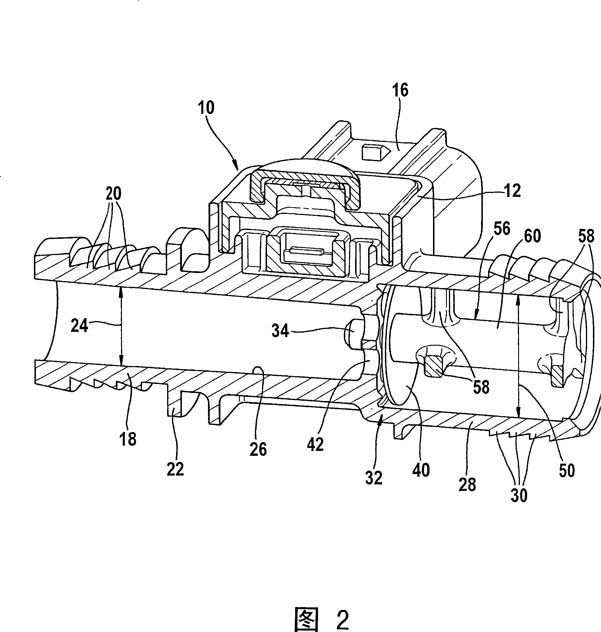
[0020] It can be seen from FIG. 1 that the pressure sensor or pressure switch 10 is inserted into a housing 12 , which is formed, for example, as an injection-molded part. The pressure sensor or pressure switch 10 is preferably inserted into a cavity 14 enclosed by the walls of the housing 12 . On the housing 12 of the pressure sensor or pressure switch 10 there is a plug connector 16 likewise formed by injection moulding, by means of which the signal of the pressure sensor or pressure switch 10 can be transmitted to an evaluation or control unit. Inside the housing 12 of the pressure sensor or pressure switch 10 there is a first connecting piece 18 , to which a pressure accumulator, for example a brake booster of a vehicle brake system, can be connected. In this embodiment, the housing 12 of the pressure sensor 10 and the first connecting piece 18 are a single component. On this component there is a second connecting piece 28 for connecting a pressure source for charging the...
PUM
 Abstract
Description
Claims
Application Information
 - R&D Engineer
- R&D Manager
- IP Professional
- Industry Leading Data Capabilities
- Powerful AI technology
- Patent DNA Extraction
Browse by: Latest US Patents, China's latest patents, Technical Efficacy Thesaurus, Application Domain, Technology Topic, Popular Technical Reports.
© 2024 PatSnap. All rights reserved.Legal|Privacy policy|Modern Slavery Act Transparency Statement|Sitemap|About US| Contact US: help@patsnap.com