
Internal combustion engine temperature regulator

A technology of temperature regulator and internal combustion engine, which is applied in the direction of engine components, machine/engine, engine cooling, etc. It can solve the problems affecting the heat dissipation of the internal combustion engine, the damage of the limit switch, and the complicated structure, so as to achieve safe performance, prolong service life, Avoid the effect of boiling the pot

Inactive Publication Date: 2008-06-04
梁国胜
View PDF0 Cites 19 Cited by
  • Summary
  • Abstract
  • Description
  • Claims
  • Application Information

AI Technical Summary

Problems solved by technology

However, due to the long-term rotation of the main and auxiliary flap shafts, the rubber rings are worn, and the cooling water enters the reduction gear box to varying degrees under the pressure generated by the water pump. On the one hand, the limit switch in the reduction gear box is damaged. Internal combustion engine cooling due to loss of cooling water
[0005] In summary, the above two points determine that the product durability, safety and service life of the invention technology have certain limitations.
[0006] 3. The large and small cycle conversion of cooling water is realized by the synchronous gear set driven by the worm gear, and then the main and auxiliary flap shafts are driven to rotate, and the main and auxiliary flaps are controlled to open or close, so the structure is cumbersome

Method used


Image

  • Internal combustion engine temperature regulator
  • Internal combustion engine temperature regulator
  • Internal combustion engine temperature regulator

Examples


Embodiment 1

[0026] The present invention will be further described below in conjunction with the accompanying drawings:

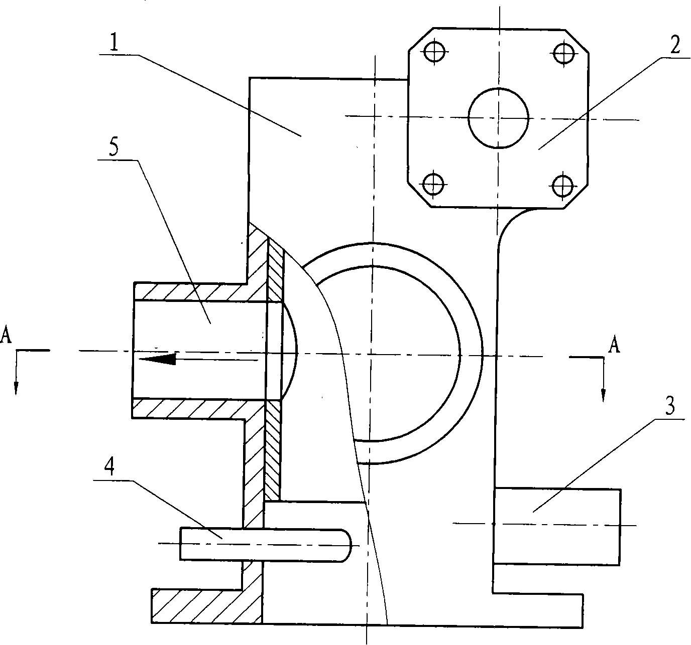
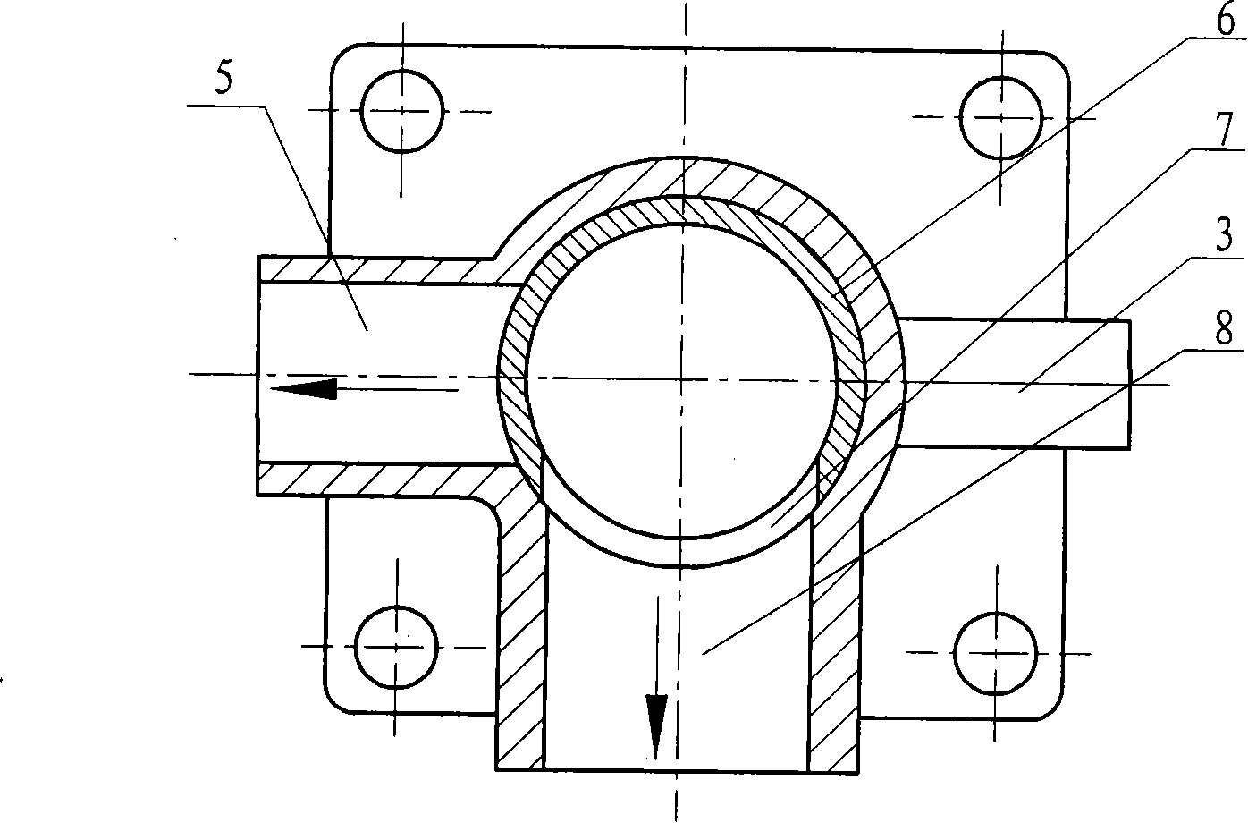
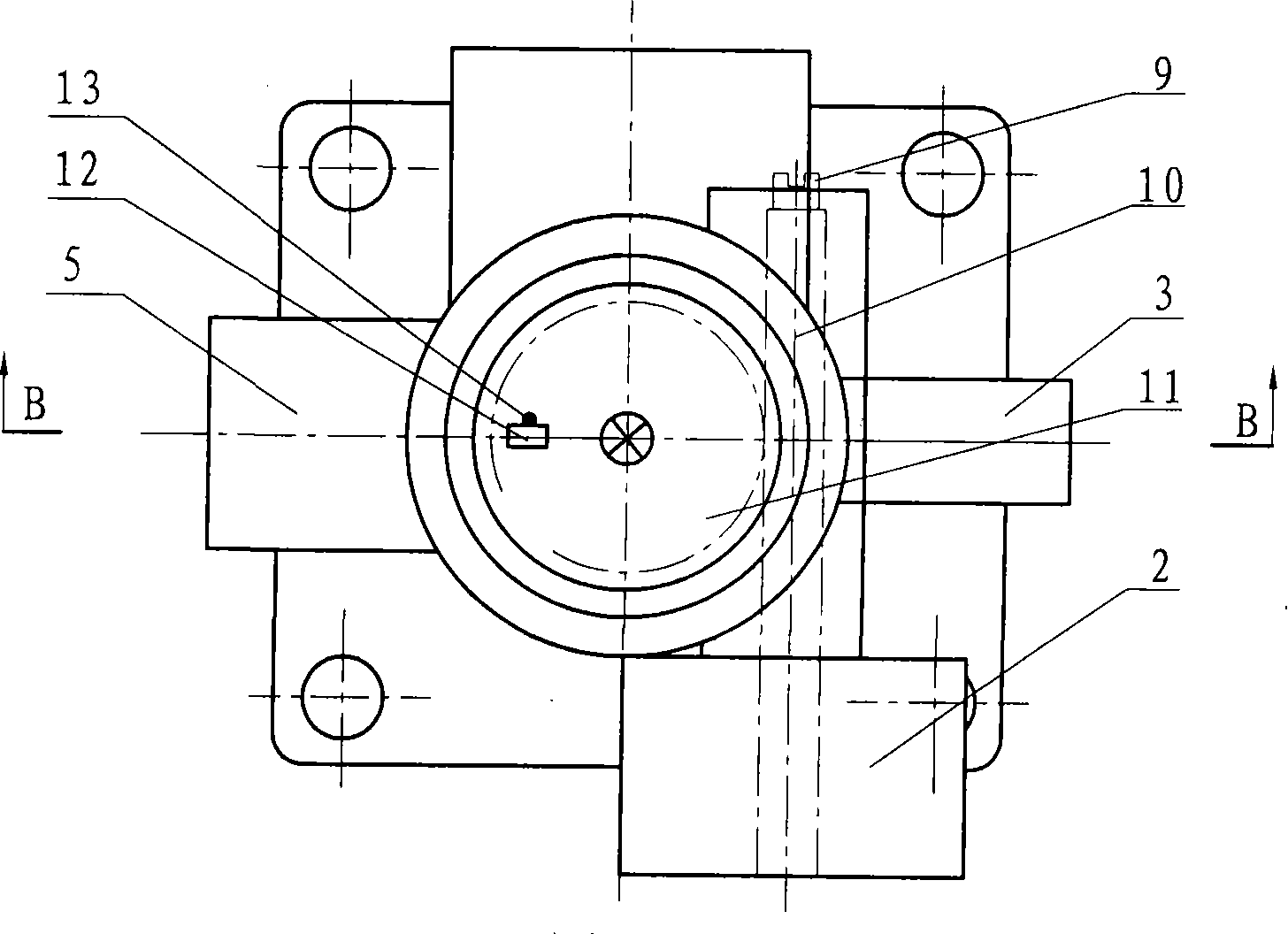
[0027] like figure 1 , 2, 3, 4, 5, 6, 1. Three-way valve body of temperature regulator, 2. Stepper motor, 3. Spare interface, 4. Temperature sensor, 5. Small circulating water outlet, 6. Rotor, 7. Rotor cooling water outlet, 8. Large circulation water outlet, 9. Manual safety knob, 10. Worm, 11. Worm gear, 12. Limit switch, 13. Limit post, 14. Valve body cover, 15. Worm gear Fixing nut, 16. Rotor shaft, 17. Shaft sleeve, 18. Mechanical seal, 19. Connecting flange, 20. Rotor inner cavity, 21. Rotor fixing nut, 22. Gearbox, 23. Microcomputer control box, 24 . Temperature display window, 25. Temperature setting button, 26. Radiator, 27. Radiator inlet pipe, 28. Internal combustion engine temperature regulator valve, 29. Body cooling water jacket, 30. Water pump, 31. Body, 32. Radiator return pipe, 33. Small circulation return pipe.

[0028] The temperature sensor insta...


PUM


Abstract

The invention provides a temperature regulator of an internal combustion engine, which belongs to the engine parts technical field, and has the characteristics that the lateral wall of a cylindrical rotor is provided with a cooling water outlet, wherein the rotor is capable of being connected with the big and the small loop water-outlets of the valve when the rotor rotates; the top end of the rotor is connected fixedly with one end of the rotor shaft, and the other end of the rotor shaft rotates in collaboration with a stepper motor via a retarder; the valve of the temperature regulator is connected with the body of the internal combustion engine via the bottom of the pedestal linking with a flange. The invention solves the inertia problem of the thermostat on the conversion of the main and the secondary valves, achieves the goal that cooling water is capable of being converted between complete greater circulation and lesser circulation only when the working temperature of the engine reaches the optimal temperature, avoids the problem of boiling for the internal combustion engine when works under climatic conditions of high temperature, keeps the tightness of the thermostat, prevents the cooling water from leaking into the radiator when the cooling water performs complete greater circulation and lesser circulation, and precisely controls the flow of the cooling water flowing through the radiator.

Description

technical field [0001] The invention belongs to the technical field of engine supporting parts. Background technique [0002] The working temperature of the internal combustion engine is overheated, the strength of the parts is reduced, the oil is deteriorated, and the wear of the parts is increased, which eventually leads to the overall decline of the power, economy, reliability and durability of the internal combustion engine. If the working temperature of the internal combustion engine is too low, the heat dissipation loss and friction loss will increase, the wear of parts will increase, the emission will deteriorate, the internal combustion engine will work rough, the power will decrease and the fuel consumption rate will increase. The optimal working temperature of an internal combustion engine is 85°C-95°C (110°C-115°C for a high-temperature engine). Until now, when the internal combustion engine works in the atmospheric natural environment, its actual working temperat...

Claims


Application Information

Patent Timeline
Patent Type & Authority Applications(China)
IPC IPC(8): F01P7/16
Inventor 梁国胜梁效
Owner 梁国胜
Learn More