Eureka AIR delivers breakthrough ideas for toughest innovation challenges, trusted by R&D personnel around the world.

Optical fiber distance measuring method and device

A distance measurement method and optical fiber technology, applied in the direction of measuring device, measuring distance, line-of-sight measurement, etc., can solve the problems of complex system, low measurement accuracy, poor reliability, etc., and achieve the effect of high demodulation accuracy

Inactive Publication Date: 2008-05-28
BEIJING INSTITUTE OF TECHNOLOGYGY
View PDF2 Cites 9 Cited by
  • Summary
  • Abstract
  • Description
  • Claims
  • Application Information

AI Technical Summary

Problems solved by technology

[0003] The purpose of the present invention is to solve the problems of low measurement accuracy, complex system and poor reliability of the existing optical fiber interference ranging method and its device, aiming to provide an optical fiber ranging method and its device with high measurement accuracy and simple structure

Method used


Image

  • Optical fiber distance measuring method and device
  • Optical fiber distance measuring method and device

Examples


Embodiment

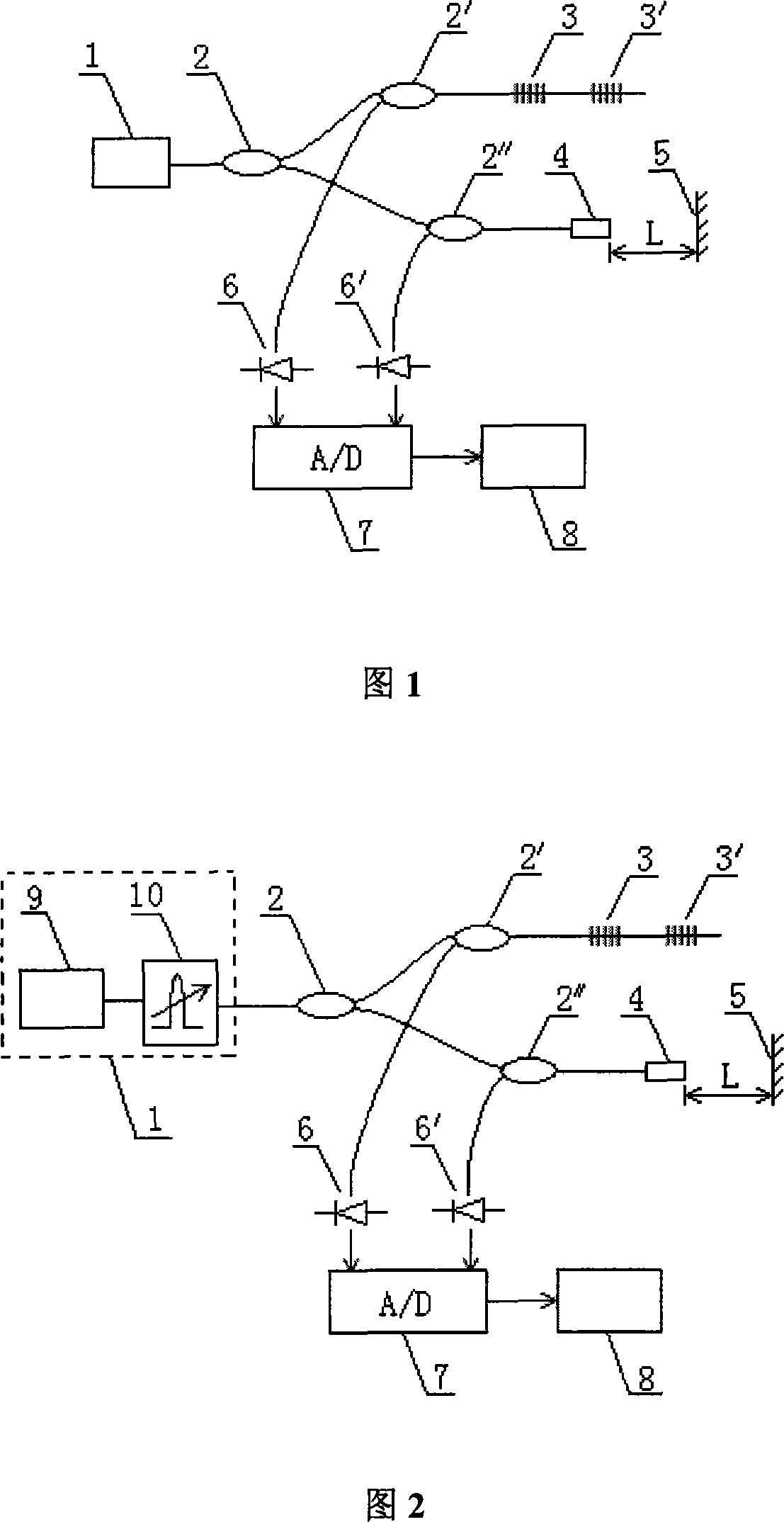
[0018] The present invention will be further described below in conjunction with embodiment. As shown in Figure 1, the output light of the wavelength scanning light source 1 is divided into two paths through a fiber coupler 2, and one path of light enters two fiber gratings 3, 3' with different center wavelengths through another fiber coupler 2'. The reflected light of the grating 3, 3' is detected by the photodetector 6; the other light enters the fiber collimator 4 through the third fiber coupler 2", and is partially reflected on the end face of the collimator 4, and the outgoing light is detected by the object to be measured Part of the surface 5 is reflected back to the fiber collimator 4, and the two beams of reflected light interfere and are detected by the photodetector 6'; the output signals of the photodetector 6, 6' are input to the computer 8 through the A / D converter 7 for processing. Scanning the light source Detect the reflected light of the fiber grating 3, 3′ t...


PUM


Abstract

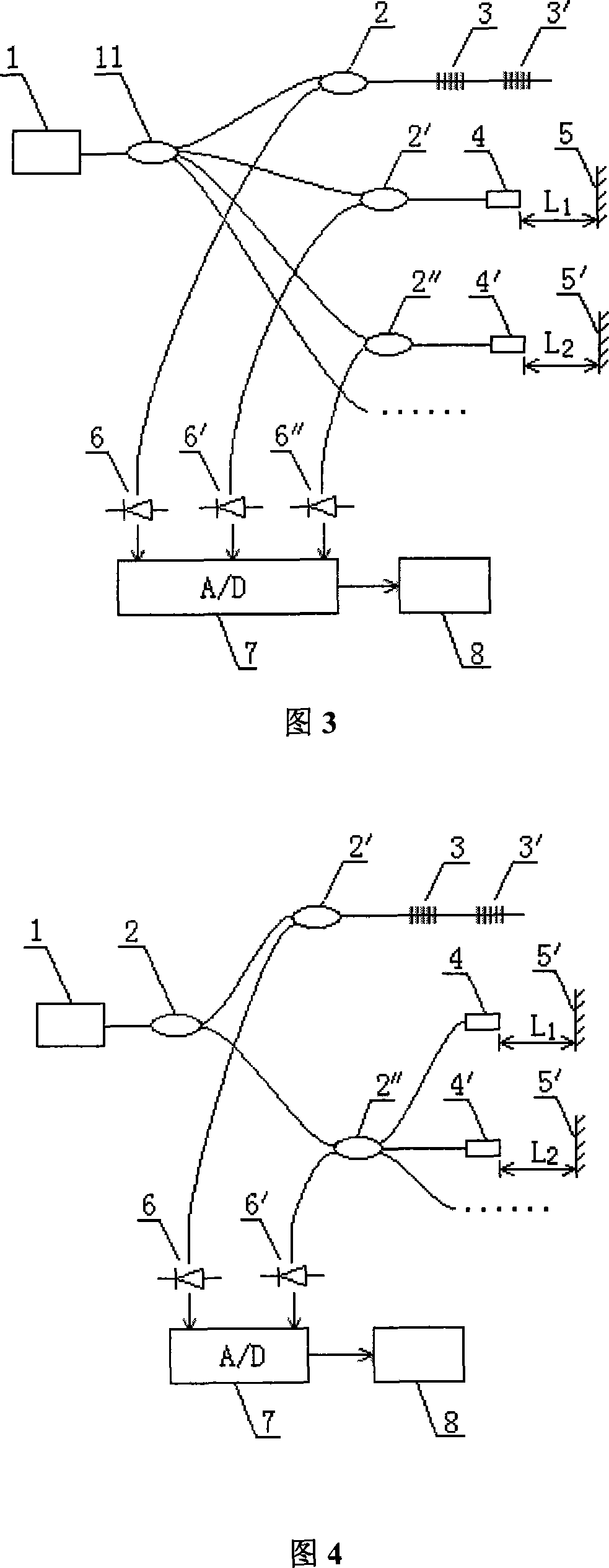
The invention relates to a distance-measuring method and a device for an optical fiber, which comprises a wavelength-scanning light source (1), fiber-optical couplers (2, 2', 2''), fiber-optical gratings (3, 3'), a fiber-optical collimating device (4), a surface of an object for measuring (5), light-sensitive detectors ( 6, 6'), an A / D convertor (7) and a computer (8). Outlet light of the wavelength-scanning light source is separated to two paths through the fiber-optical couplers, one light path enters into the two fiber-optical gratings whose central wave length are different, reflected light of the fiber-optical gratings are detected by the light-sensitive detectors, the other path which enters into the fiber-optical collimating device is partially reflected by the end surface portion of the collimating device, the reflected light is partially reflected return to the fiber-optical collimating device by the surface of the object for measuring, two beams of the reflected light are detected by the light-sensitive detectors after being interfered. Output signal of the light-sensitive detectors is input into the computer through the A / D convertor, an distance between the end surface of the fiber-optical collimating device and the surface of an object for measuring is calculated through fourier transform white light interferometric phase demodulation method.

Description

technical field [0001] The invention belongs to the technical field of optical distance measurement, in particular to an optical fiber distance measurement method and a device thereof. Background technique [0002] High-precision absolute distance measurement is an important development direction of today's measurement technology. In order to improve the measurement accuracy and realize the non-contact absolute distance measurement, people have introduced optical interference technology; at the same time, in order to reduce the volume of the measuring instrument, simplify the structure of the optical path and improve the stability of the optical path, combined with the optical fiber sensing technology, the optical fiber interferometry is proposed. The method and apparatus (CN 1095536C, CN 1147702C) of distance. Optical fiber interferometric ranging can adopt the structure of Mach-Zehnder, Michelson or Fabry-Perot interferometer (actually Fizeau interferometer), in which the...

Claims


Application Information

Patent Timeline
Patent Type & Authority Applications(China)
IPC IPC(8): G01C3/00G01C3/08G02B6/26G02B6/34
Inventor 江毅唐才杰
Owner BEIJING INSTITUTE OF TECHNOLOGYGY
Why Eureka
Eureka Blog
Learn More