Quasimolecule light irradiator
An excimer and light irradiation technology, applied in the field of excimer light irradiators, can solve problems such as reducing the operation rate of production plants, and achieve the effects of improving the operation rate, ensuring light irradiation, and ensuring lifespan
- Summary
- Abstract
- Description
- Claims
- Application Information
AI Technical Summary
Problems solved by technology
Method used
Image


Examples
Embodiment 1
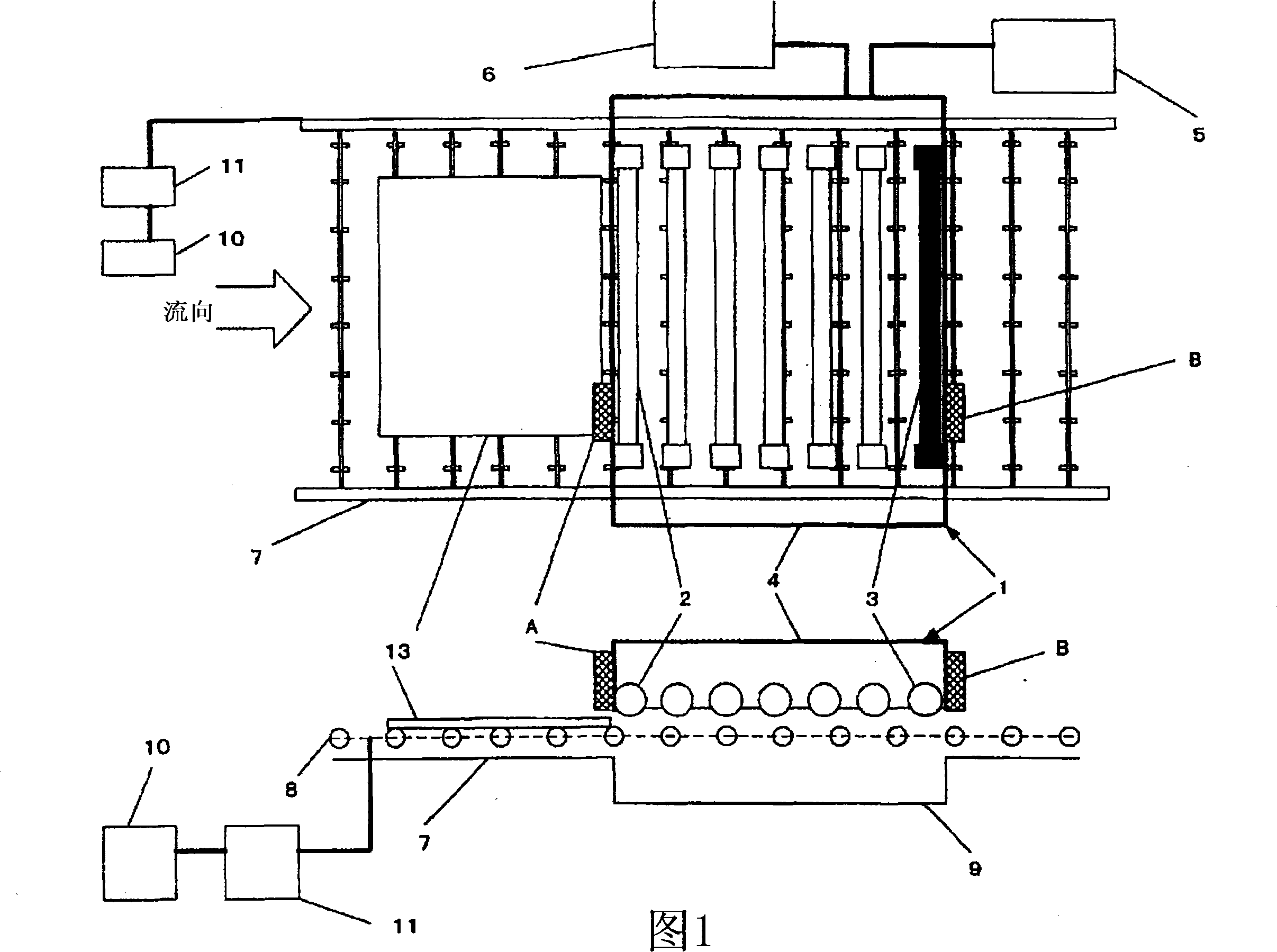
[0033]First Embodiment An example in which the present invention is applied to a liquid crystal substrate cleaning device is shown in FIG. 1 as a substrate processing device equipped with an excimer light irradiator. Fig. 1 will be described. 1 shows a view in which the light-irradiated surface of the substrate 13 to be processed faces upward on the paper, and a schematic cross-sectional view (lower view) in a direction perpendicular to the tube axis direction of the excimer lamp 2 . 1 is the main body of the excimer light irradiator. The excimer light irradiator main body 1 consists of an excimer lamp 2, a spare lamp 3, a light box 4 in which the lamp is installed, and an electrical installation part (electrical installation part) for controlling the lighting of the lamp. 5. And a display 6 for displaying each lighting condition, lighting state, and abnormal state. Further, the substrate transfer device 7 is composed of a transfer roller ring 8 for transferring the substrate...
Embodiment 2
[0036] FIG. 2 shows this excimer photoirradiator provided with a plurality of backup lamps as another embodiment of the present invention. 2-a) is a cross-sectional view of a plane perpendicular to the lamp tube axis, in which a square excimer lamp 22 and a spare lamp 23 of the same square shape are arranged side by side in a light box 21 . 2-a) is a schematic layout view of the excimer light irradiator viewed from above and a cross-sectional view of a plane perpendicular to the tube axis of the excimer lamp 22 . In this embodiment, the excimer lamps 22 are arranged so as to partially overlap in the width direction of the substrate to be processed, and two excimer lamps 22 irradiate the entire width direction. Three groups of excimer lamps 22 are arranged side by side, and a predetermined light output is ensured as excimer lamps 22 for general use arranged to satisfy a predetermined processing capacity. In addition, two sets of backup lamps 23 set in the same manner in the wi...
Embodiment 3
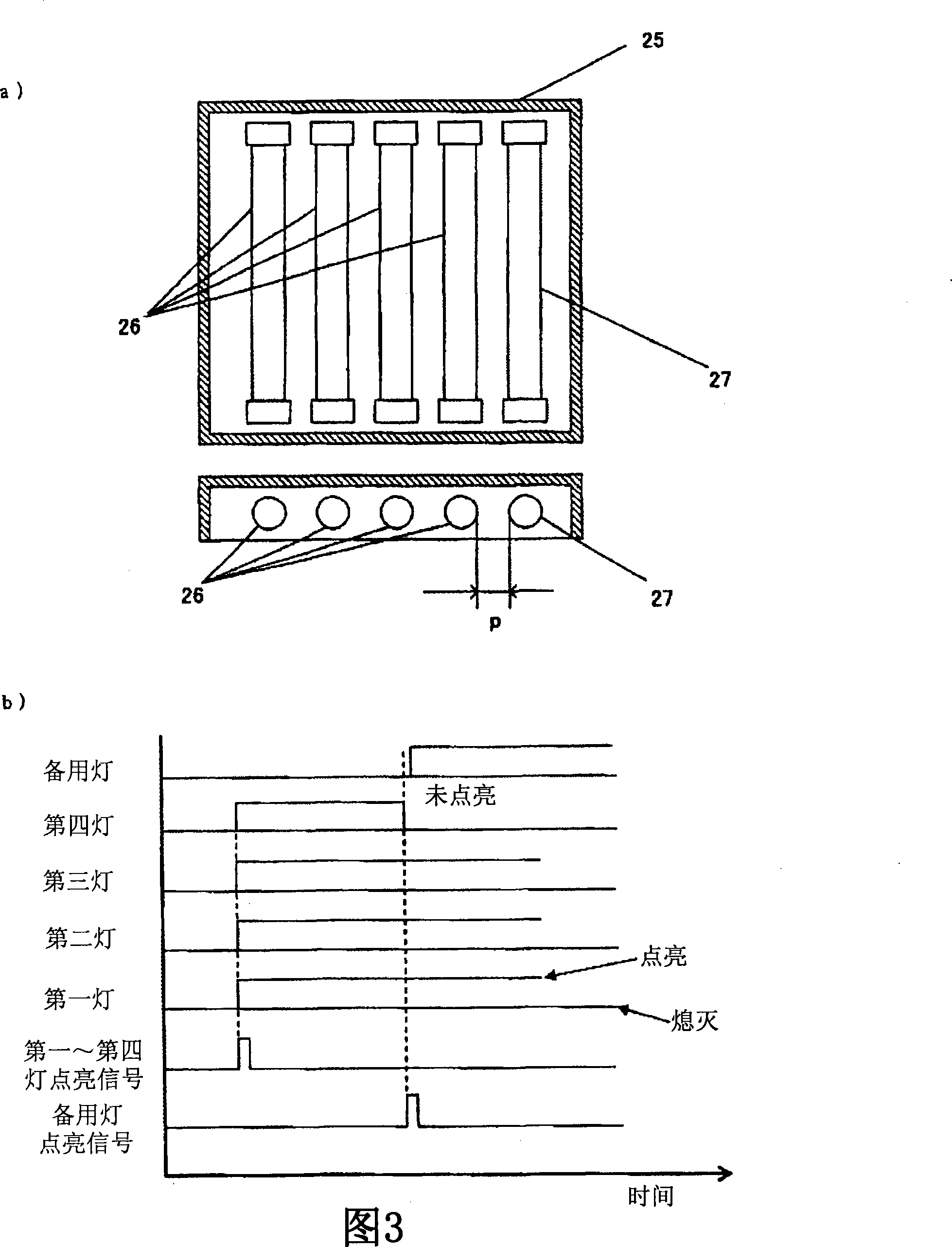
[0039] Fig. 3 is a timing chart showing the lighting timing of the excimer lamp and the backup lamp of the present invention. Fig. 3-a) is the excimer light irradiator when four excimer lamps 26 are arranged side by side in the light box 25 as common excimer lamps, and one spare lamp 27 is arranged on the downstream side of the conveying direction of the substrate to be processed 25 sketches. In addition, FIG. 3-b) is a timing chart of lighting timing corresponding to the layout shown in a). In Fig. 3-b), in the configuration diagram shown in a), the left side of this excimer lamp 26 is set as upstream, and each excimer lamp 26 is set as the first lamp, the second lamp, the third lamp from the left end. lamp, the fourth lamp. The horizontal axis of Figure 3-b) is the time axis. When the lighting signals of the first lamp to the fourth lamp are input, the excimer lamps from the first lamp to the fourth lamp are turned on. Here, if the fourth lamp is not lit, it is detected ...
PUM
 Abstract
Description
Claims
Application Information
 - Generate Ideas
- Intellectual Property
- Life Sciences
- Materials
- Tech Scout
- Unparalleled Data Quality
- Higher Quality Content
- 60% Fewer Hallucinations
Browse by: Latest US Patents, China's latest patents, Technical Efficacy Thesaurus, Application Domain, Technology Topic, Popular Technical Reports.
© 2025 PatSnap. All rights reserved.Legal|Privacy policy|Modern Slavery Act Transparency Statement|Sitemap|About US| Contact US: help@patsnap.com