
Method and System for Monitoring an Aircraft Taxiing Phase

Active Publication Date: 2010-05-06
THALES SA
View PDF2 Cites 23 Cited by
  • Summary
  • Abstract
  • Description
  • Claims
  • Application Information

AI Technical Summary

Benefits of technology

[0019]The aim of the invention is to improve the safety of the taxiing phases by verifying the taxi plan with respect to the data contained in the various onboard databases, and by notifying the pilot of the result of these verifications. Moreover, this method verifies whether the essential clearances exist in the taxi plan. If this is not the case, it proposes to the pilot that these clearances be inserted into the taxi plan.
[0026]The invention is advantageous in the sense that it allows the taxi constraints to be taken into account rapidly so as to signal them to the pilots in an opportune manner, thereby avoiding a search through the airport documentation. Moreover, the item of information resulting from the verification of the taxi plan is adapted according to the aircraft's proximity to the element. The display for aiding taxiing describes on the taxi plan the pathway constraints associated with the taxi elements along the pathway. Another advantage resulting from the monitoring method is the detection of erroneous taxi plan thus improving the safety of taxiing on the airport zone.
[0027]Advantageously, the step of monitoring the taxi authorizations d) comprises the following substeps: determination of the next taxi authorization of the active taxi element, announcement of the taxi authorization and of the time required to reach it, display on the taxi aid of an overstepping alert signalling when the aircraft is in an immediate proximity to the taxi authorization. The method also formulates a signalling to the pilot of the next clearance intervening subsequently in the taxi plan. This signalling is of alert type if the aircraft is located in immediate proximity to a clearance and of recommendation type if the aircraft is close to a clearance. This clearance monitoring advantageously makes it possible to avoid stopping the aeroplane unnecessarily at the clearance stop point, by allowing better anticipation, which may then be a source of fuel saving.
[0028]Advantageously, when step c) detects that the aircraft is located on a taxi element not belonging to the taxi plan, the method carries out the following steps: display on the taxi aid of an alert presenting the discrepancy of the location of the aircraft with respect to the pathway plan, step a) of testing the pathway constraints of the active taxi element, step b) of testing the taxi authorizations for the active taxi element and step d) of monitoring the taxi authorization of the active taxi element. Thus the invention makes it possible to detect any straying of the aircraft from the taxi plan and to signal the constraints and clearance ahead of the aircraft which had not initially been envisaged.

Problems solved by technology

The complexity of the large airport platforms associated with considerable and rapidly growing traffic, is making the taxiing phase into an increasingly tricky phase for pilots notably when they have limited experience of this airport and its constraints.
This may lead to errors of assessment, and the aeroplane may be in zones where it is not authorized, entailing risks of collisions.
Currently, within the framework of the airport phases, the distribution of the on-board / ground control responsibilities, the operational procedures, the density of the traffic and the considerable number of parties on the airport platform do not enable an aircraft to employ equipment having the capacity to assimilate all the information in order to move in an optimal manner.
The problem with the construction of the taxi plan is that it may then be erroneous or that it may lack information, notably stop points to wait for authorizations.
But these functions ensure only limited monitoring, relying as they do exclusively on databases describing the geometry of the airport with respect to the current position of the aeroplane, and not to the rules of use dictated (and modified periodically) by the local control authorities and specifically established over the pathway envisaged by the aeroplane.
Moreover, the segregation of the equipment used during the taxiing phases, prevents these messages from being correlated with pathway information formulated through a routing means or a richer database having all the information about the airport surface.

Method used


Image

  • Method and System for Monitoring an Aircraft Taxiing Phase
  • Method and System for Monitoring an Aircraft Taxiing Phase
  • Method and System for Monitoring an Aircraft Taxiing Phase

Examples


Embodiment Construction

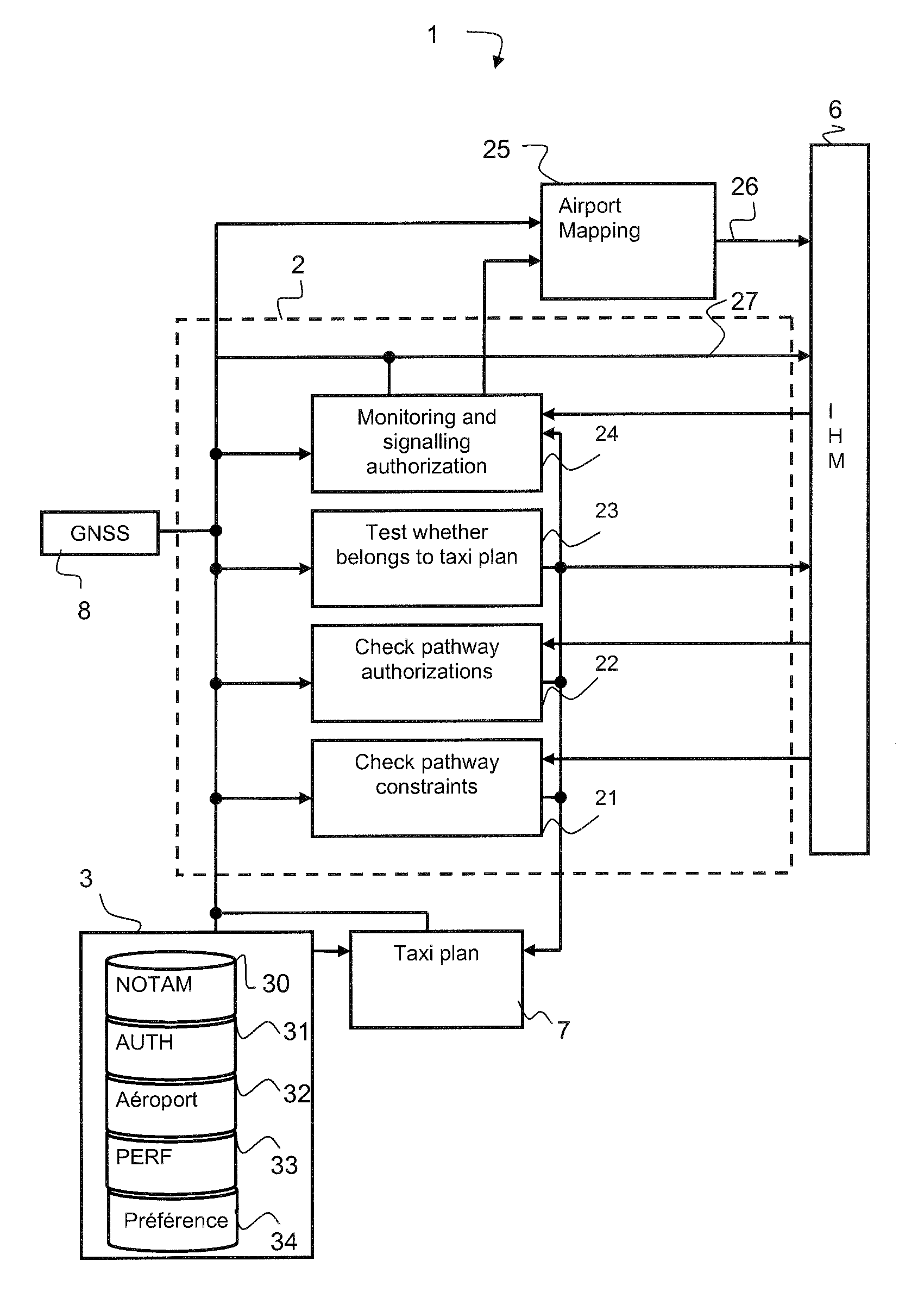
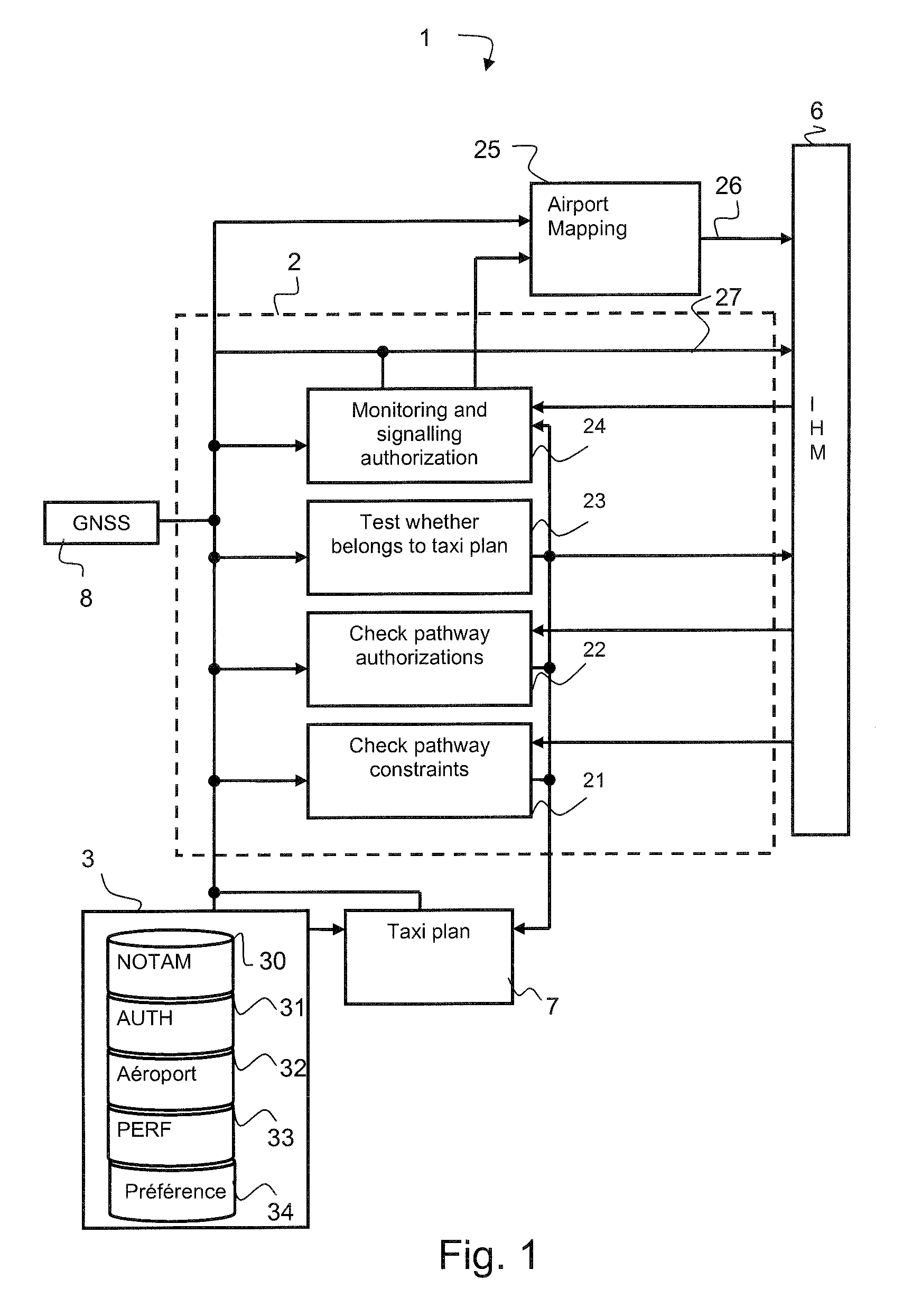
[0040]The first part of the description presents the hardware architecture, shown diagrammatically by FIG. 1, on which the monitoring method relies. The objective of this first part is to describe the data manipulated for the monitoring application and the systems producing these data. A second part of the description subsequently describes the functions of the monitoring system making it possible to aid the pilot in the management of the taxiing phase.

[0041]The pathway monitoring system 1 comprises a calculation device 2 comprising checking devices 21 to 24 implementing the monitoring functions of the monitoring method. For the formulation of these functions, the calculation device is connected to a database system 3, to a man-machine interface device 6 (MMI), to a taxi plan formulation device 7 and to a geo-location device 8.

[0042]The function of the MMI 6 is to present to the crew the taxi plan of the aircraft from the boarding zone to the takeoff runway during the takeoff phase ...


PUM


Abstract

The invention relates to the field of monitoring and aid to taxiing of an aircraft at an airport.The invention is a method of checking and monitoring the taxi plan and relates to a monitoring system comprising means for checking the pathway of the plan and means for signalling on the taxi aid the waiting time for the next clearance ahead of the aircraft along the pathway, the means for checking the pathway comprising a device for checking the pathway constraints and a device for checking the clearances, the device for checking the constraints making it possible to test and to display on the taxi plan the information descriptive of the constraints and the device for checking the clearances making it possible to check the clearances and to add the missing clearances to the taxi plan.

Description

PRIORITY CLAIM[0001]This application claims priority to French Patent Application Number 08 05841, entitled Method and System for Monitoring an Aircraft Taxiing Phase, filed on Oct. 22, 2008.FIELD OF THE INVENTION[0002]The field of the invention is that of monitoring and aid afforded to the pilot in the phase during which an aircraft is rolling over the ground at an airport.BACKGROUND OF THE INVENTION[0003]The complexity of the large airport platforms associated with considerable and rapidly growing traffic, is making the taxiing phase into an increasingly tricky phase for pilots notably when they have limited experience of this airport and its constraints. The pilot must manoeuvre the aeroplane along a pathway comprising numerous intersections whilst monitoring the traffic, while complying with the controller's taxi authorizations, usually called clearances, and while making preparations for takeoff. This may lead to errors of assessment, and the aeroplane may be in zones where it ...

Claims


Application Information

Patent Timeline
IPC IPC(8): G06F17/30
CPCG08G5/0021G08G5/065
Inventor GAYRAUD, PASCALMARTY, NICOLASDUBOURG, BERNARDMICHEL, FRANCOIS
Owner THALES SA
Learn More