
Curved sliding vane type rotary compressor

A rotary compressor and sliding vane technology, used in rotary piston machinery, rotary piston pumps, mechanical equipment, etc., can solve problems such as increased leakage, difficulty in smoothness of sealing parts, and wear at chamfers. Achieve the effect of small mechanical wear, small leakage and stable operation

Inactive Publication Date: 2008-05-28
李东林
View PDF0 Cites 7 Cited by
  • Summary
  • Abstract
  • Description
  • Claims
  • Application Information

AI Technical Summary

Problems solved by technology

[0005] The technical problem to be solved by the present invention is that the radial and axial working end faces of the cylinder block, rotor and sliding vane in the prior art are generally connected at right angles, which makes it difficult for the smoothness of the sealing parts and causes chamfering. The defects of severe wear and increased leakage, provide a curved sliding vane rotary compressor with a smooth transition between the radial and axial working end faces of the cylinder block, rotor and sliding vane, and its sealing effect is close to that of the reciprocating piston structure

Method used

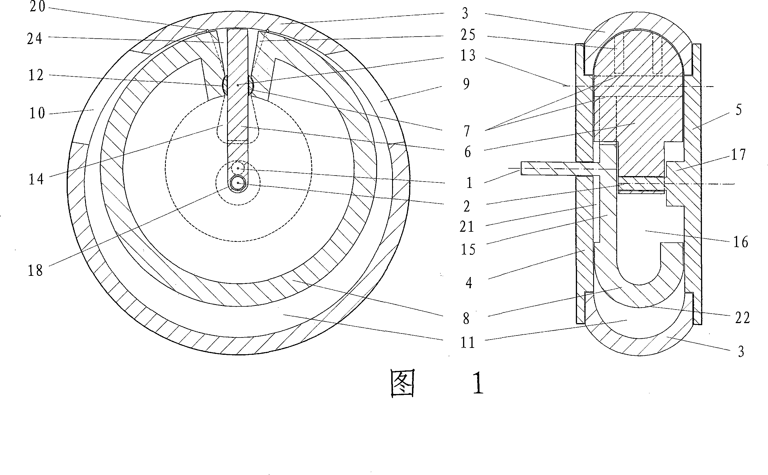
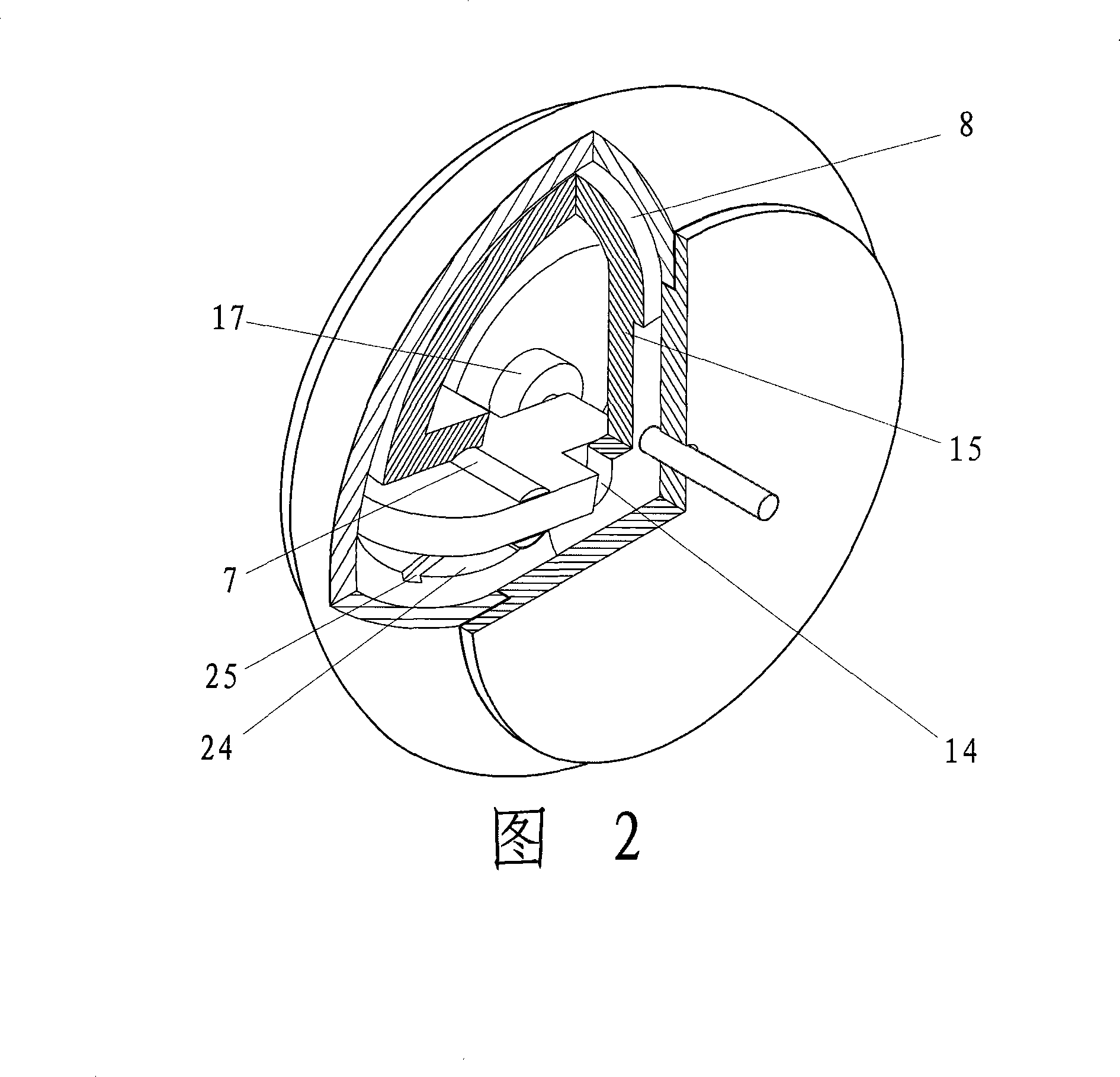
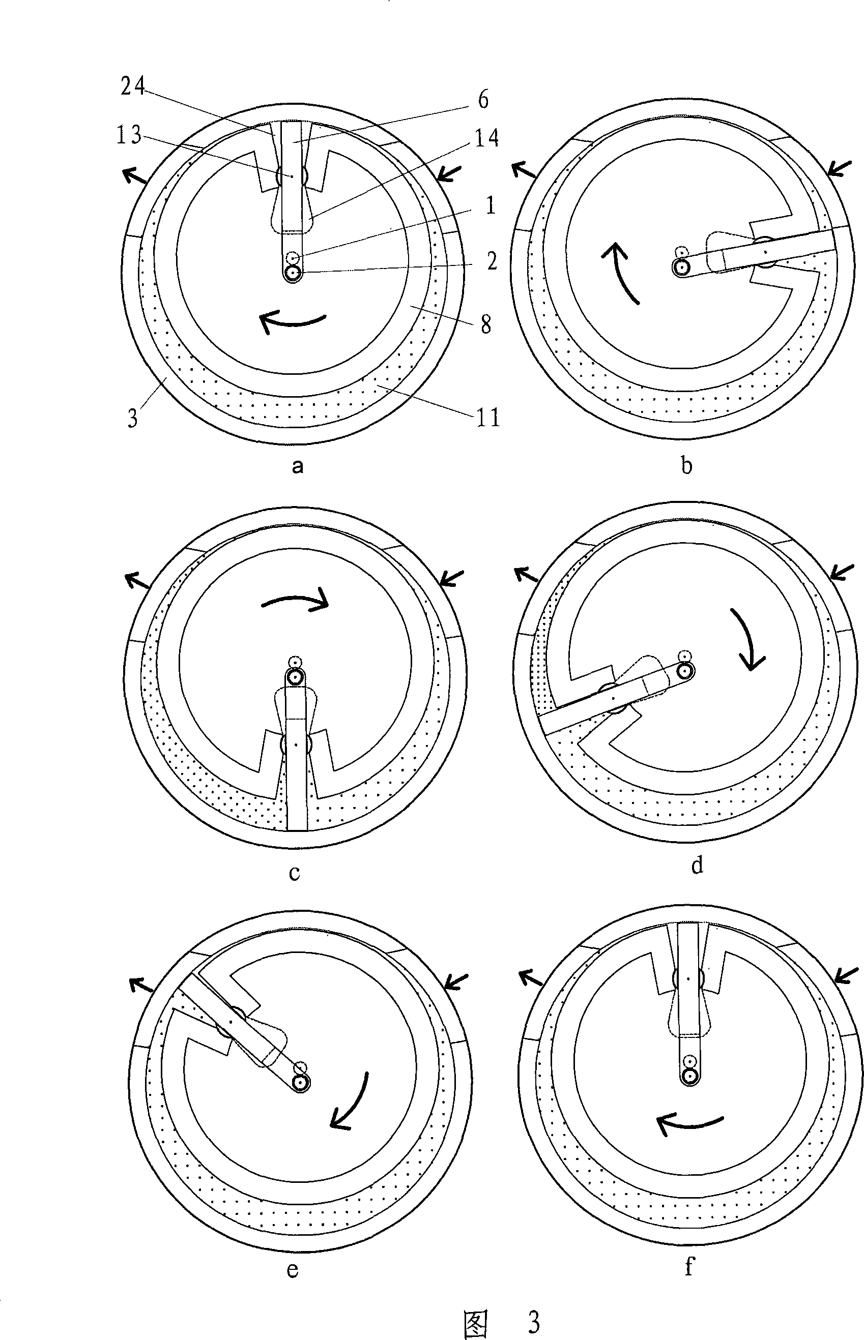

Image

  • Curved sliding vane type rotary compressor
  • Curved sliding vane type rotary compressor
  • Curved sliding vane type rotary compressor

Examples


Embodiment Construction

[0034] 1, 2, 5, the compressor of the present invention includes a cylinder block 3, a first end cover 4 and a second end cover 5 to form a compressor shell, in this embodiment, the first end cover is the front end cover 4, and the second end cover is Two end caps are rear end caps 5. The cylinder block 3 is in the shape of a ring, and its radial inner end surface is an inward annular curved surface, which is connected tangentially to the axial inner wall surfaces of the disc-shaped front end cover 4 and rear end cover 5 at its proximal part It encloses the inner chamber of the compressor, and the tangent point is 28 (see Fig. 4b). In this embodiment, the curved surface is a curved surface in the shape of an outer torus of a circular ring. It can be understood that the curved surface can also be a curved surface of other shapes, such as an ellipsoid, a paraboloid of revolution, and the like. There is an air inlet 9 and an exhaust port 10 on the cylinder block 3, a cylindrical...


PUM


Abstract

The invention relates to a curved slide vane rotating compressor, comprising a circular cylinder body, a first end cap, a second end cap, a circular rotor, and at least one slide vane. The radial inner end face of the cylinder body is a ring-shaped curved face, and is respectively and smoothly connected with axial inner walls of the first and the second end caps. The radial outer end face of the rotor is a curved face which is hermetically engaged with the radial inner end face of the cylinder body, and is respectively and smoothly connected with the axial end faces on the two sides of the rotor. The radial outer end face of the slide vane is a curved face which is hermetically engaged with the radial inner end face of the cylinder body, and is respectively and smoothly connected with the axial end faces on the two sides of the slide vane. The axial end faces on the two sides of the rotor are respectively and hermetically engaged with the inner walls of the first and the second end caps, and the axial end faces on the two sides of the slide vane are respectively and hermetically engaged with the axial inner walls of the first and the second end caps. The invention removes a connecting edge angle, and the working face of a sealing element such as the slide vane, the rotor and the cylinder body is excessively smoothed, which has the advantages of favorable low speed performance, small machinery damage, less leakage, and long service life and the like.

Description

technical field [0001] The invention relates to a rotary vane type fluid machine, more specifically, a curved vane type rotary compression machine suitable for compressors, pumps and motors. Background technique [0002] Rotary vane compressors (including other vane fluid machines) have the advantages of simple structure, stable operation, and high efficiency, and are widely used in various industries. However, the rotary vane compressor also has some disadvantages, which limit its development, such as poor low-speed performance, large mechanical wear, increased leakage, and reduced service life. The important factors that form the above defects are: [0003] 1. The radial and axial working end faces of the cylinder block, rotor and sliding vane of the sliding vane compressor are generally connected at right angles, which causes difficulties in the smoothness of the sealing parts, causing serious wear at the chamfers, and the amount of leakage increase. The most widely us...

Claims


Application Information

Patent Timeline
IPC IPC(8): F04C18/344F04C27/00
Inventor 李东林
Owner 李东林
Learn More