
Composite absorption heat pump

A two-stage absorber, one-stage technology, applied in heat pumps, energy-saving heating/cooling, lighting and heating equipment, etc., can solve the problems of not being able to fully utilize the driving heat and cooling capacity, complicating the overall system, and failing to meet heat demand

Active Publication Date: 2008-05-21
李华玉
View PDF0 Cites 10 Cited by
  • Summary
  • Abstract
  • Description
  • Claims
  • Application Information

AI Technical Summary

Problems solved by technology

When the amount of waste heat resources is small, the temperature is low, or the temperature required by the heat user is high and the range is wide - when it is necessary to heat the heated medium from a low temperature to a high temperature, a single-stage heat pump often cannot To achieve the effect of not only meeting the heat demand of heat users, but also having a high performance index, which cannot maximize the energy-saving benefits
[0005] When waste heat cooling is used, when the cooling requirements and the initial parameters of the driving heat are determined, units using a single stage often cannot make full use of the driving heat to obtain more cooling capacity, especially when using waste heat cooling——single stage The number of units cannot fully and effectively utilize the waste heat
[0006] Using units with different stages to form a joint heat pump system or a joint refrigeration system can achieve higher heating or cooling benefits, but this will bring complexity and high costs to the overall system

Method used


Image

  • Composite absorption heat pump
  • Composite absorption heat pump
  • Composite absorption heat pump

Examples


Embodiment Construction

[0019] The present invention will be described in detail below in conjunction with the accompanying drawings and examples.

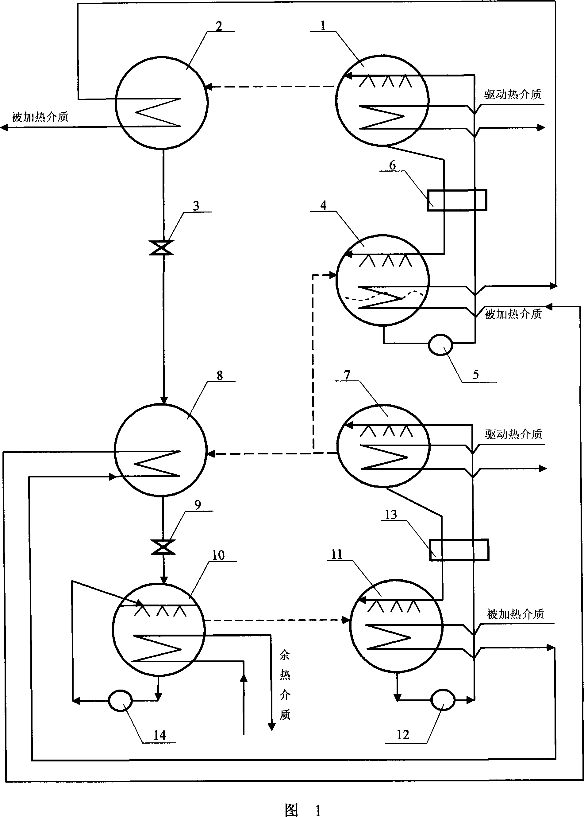
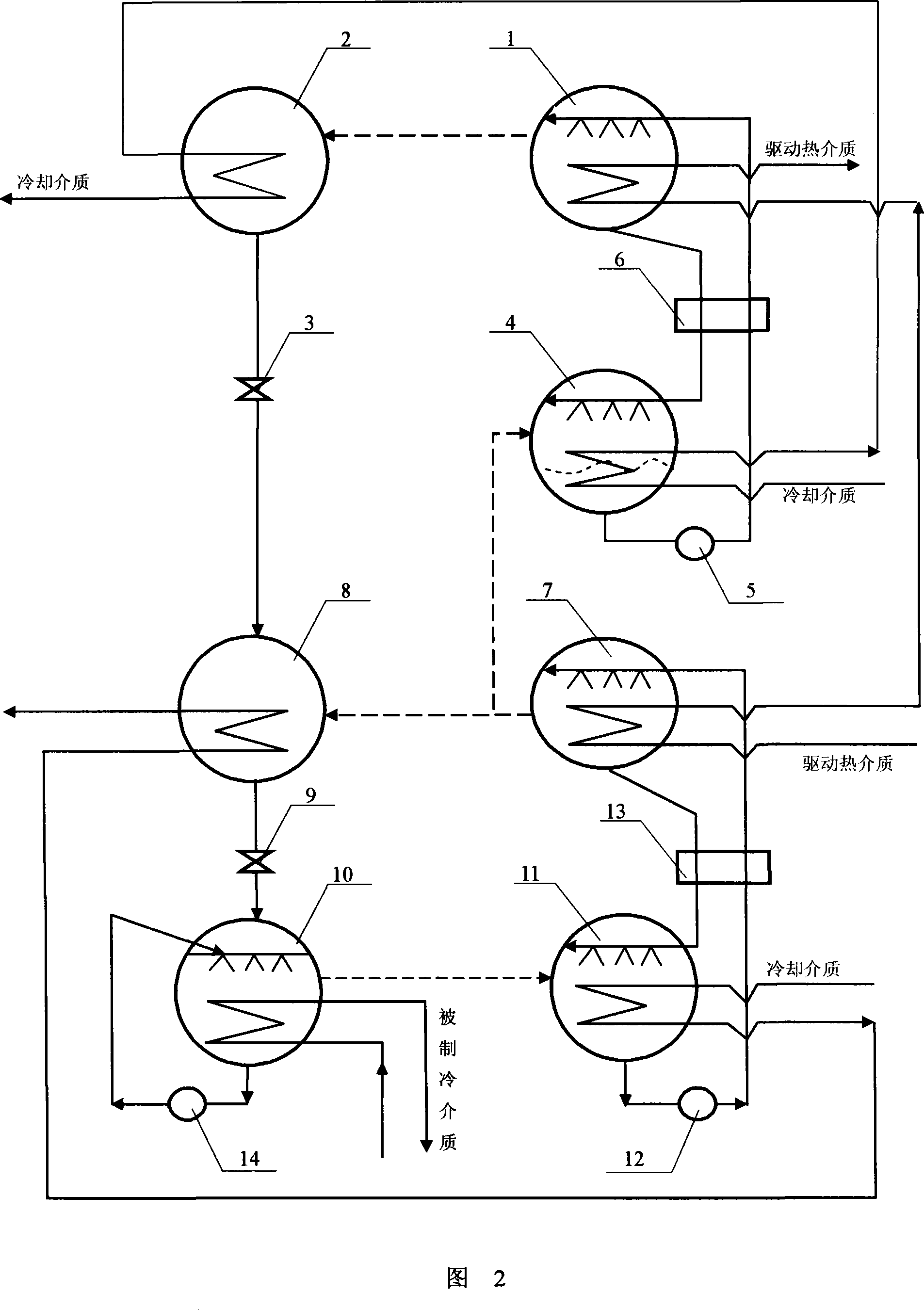
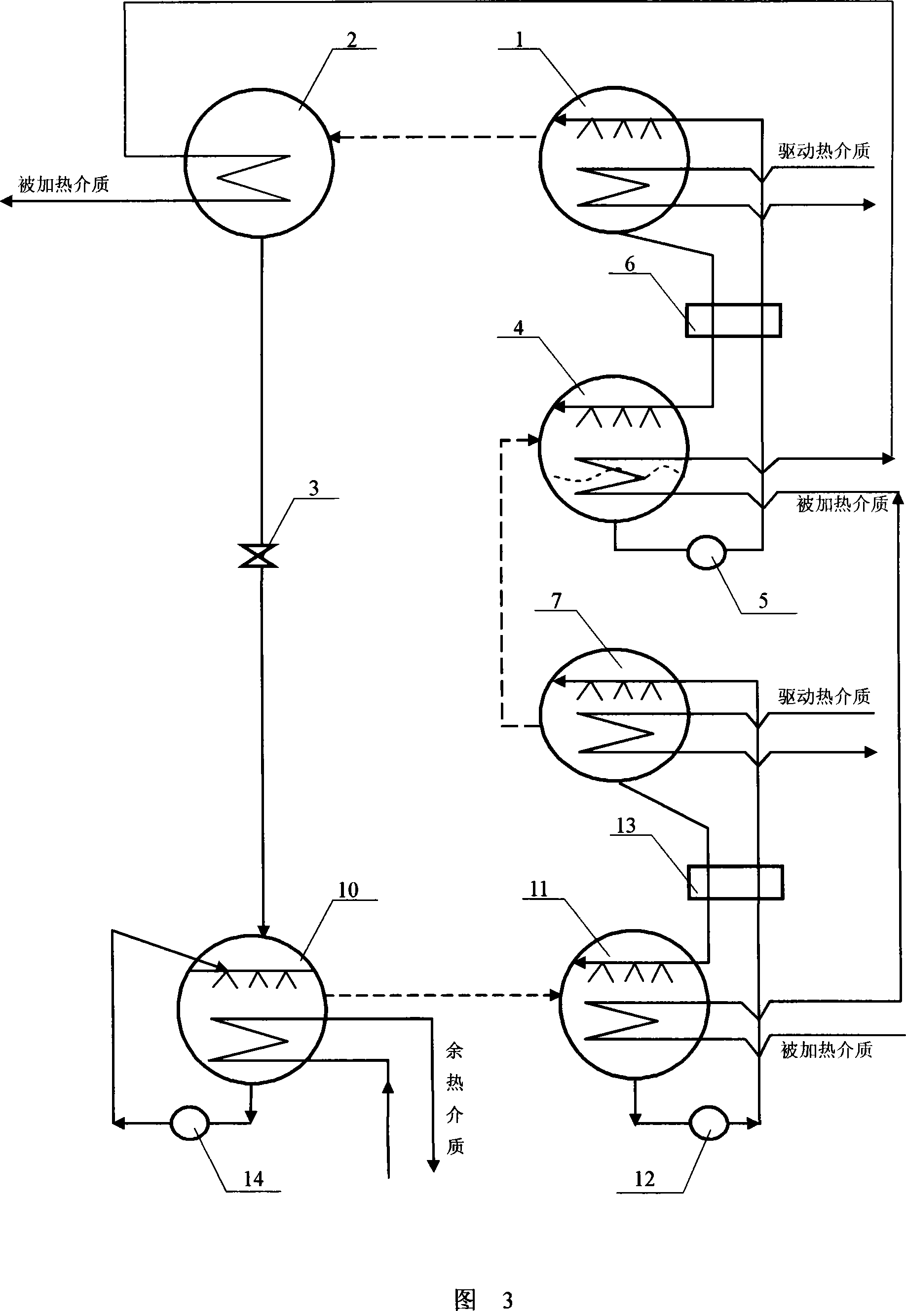
[0020] Taking the composite absorption heat pump provided according to the present invention, which can realize the functions of primary and secondary composite heat pumps, as an example, as shown in Figure 1, the purpose of the present invention is achieved in this way:

[0021] The present invention consists of secondary generator 1, secondary condenser 2, throttle valve 3, secondary absorber 4, solution pump 5, solution heat exchanger 6, primary generator 7, primary condenser 8, section Flow valve 9, evaporator 10, primary absorber 11, solution pump 12, solution heat exchanger 13 and refrigerant liquid recirculation pump 14;

[0022]Primary generator 7, primary condenser 8, throttle valve 9, evaporator 10, primary absorber 11, solution pump 12 and solution heat exchanger 13 form a primary heat pump process and structure——primary generator 7 It is con...


PUM


Abstract

The invention provides a compound-typed first class absorption heat pump and belongs to the technical field of waste heat utilization and heat pump / refrigeration. The invention aims at the shortcomingof the single class heat pump and provides a compound integrated type machine set mainly consisting of a first class generator, a second class generator, a first class condenser, a second class condenser, a first class absorber, a second class absorber, an evaporator, a throttle, a solution pump and other basic components. A first class heat pump procedure with high performance index and a low temperature heat supply section consists of the first class generator, the first class condenser, the throttle, the evaporator, the solution pump and the first class absorber; the second class generator, the second class condenser, the throttle, the solution pump and the absorber form a second class heat pump procedure with a high temperature heat supply section and low performance index with the help of the first class procedure; wherein, the second class condenser is communicated with the first class condenser through the throttle and the first class generator is communicated with the second class absorber through a refrigerant evaporation channel; the heat pump can fully take use of the waste heat and has higher energy-saving benefit when in the high temperature heat supply in a wide temperature range; the waste heat refrigeration can make use of driven heat deeply.

Description

Technical field: [0001] The invention belongs to the technical field of low-temperature waste heat utilization and heat pump / refrigeration. Background technique: [0002] The use of absorption heat pump / refrigeration technology for waste heat utilization is an effective means, which has many benefits such as energy saving, environmental protection and economy. On the premise of meeting the needs of users, it is necessary to ensure that the unit has a high performance index and to realize the simplification of the unit / system structure and process, which is the development direction of absorption technology. [0003] For absorption heat pump / refrigeration technology, there is a mutually restrictive relationship between the working parameters of the unit and its performance index. For example, in the first type of absorption heat pump, the units with low stages have low heating temperature and high performance index, and the units with high stages have high heating temperatur...

Claims


Application Information

Patent Timeline
Patent Type & Authority Applications(China)
IPC IPC(8): F25B30/04
CPCY02B30/62Y02A30/27
Inventor 李华玉
Owner 李华玉
Learn More