
Inlet seriously distorted lower asymmetric unsteady generator

An asymmetric and generator technology, applied to aircraft parts, aircraft power units, aircraft power unit components, etc., can solve the problem of reducing the aerodynamic efficiency of the compressor, the asymmetry of the flow field around the separation of the compressor, and the lack of consideration of intake distortion Problems such as flow field asymmetry, to achieve the effect of improving the stability margin

Inactive Publication Date: 2008-05-21
廊坊智驰动力科技有限公司
View PDF0 Cites 8 Cited by
  • Summary
  • Abstract
  • Description
  • Claims
  • Application Information

AI Technical Summary

Problems solved by technology

[0006] There are two main defects in the traditional processing casing: on the one hand, there is relative motion between the processing casing and the compressor rotor, the flow field of the compressor with the processing casing is strongly unsteady, and the unsteady components of the processing The steady separation flow interaction will inevitably affect the stability expansion function of the processing casing. The traditional processing casing does not consider the unsteady interaction of the processing casing / compressor rotor; on the other hand, under the condition of distorted and asymmetric incoming flow, the Position work under different aerodynamic load conditions, the flow field around the separation of the compressor is seriously asymmetrical, and the traditional treatment casing treatment slots are evenly distributed throughout the circumference, without considering the asymmetry of the intake distortion flow field
Based on the above two points, the traditional processing casing cannot obtain a satisfactory expansion effect: that is, on the basis of expanding the stable working range of the compressor, the aerodynamic efficiency of the compressor is reduced

Method used


Image

  • Inlet seriously distorted lower asymmetric unsteady generator
  • Inlet seriously distorted lower asymmetric unsteady generator

Examples


Embodiment Construction

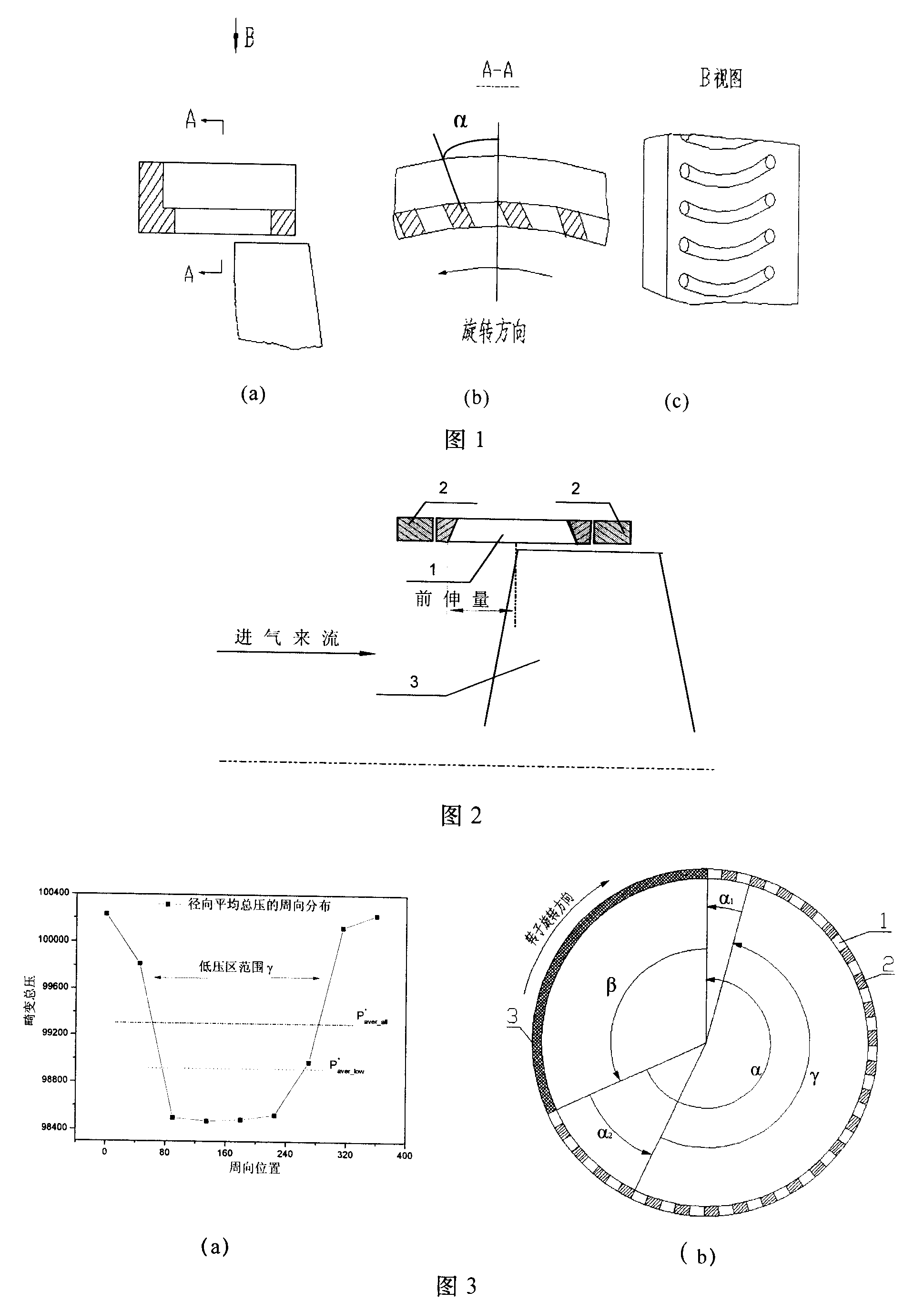
[0018] In order to describe the present invention more clearly, a typical embodiment of the unsteady generator for the asymmetric casing under severe inlet distortion of the present invention will be described below with reference to the accompanying drawings.

[0019] Fig. 2 is an axial sectional view of the unsteady generator of the asymmetric casing under serious inlet distortion according to the present invention. This asymmetric casing unsteady generator is composed of a processing ring and several distance adjusting rings. The processing ring is above the rotor blades of the compressor, and several distance adjustment rings are used to adjust the protruding amount of the crescent chute processing casing.

[0020] When using the processing case to improve the aerodynamic performance of the compressor, by adjusting the axial length of the distance adjusting ring, the processing ring moves forward or backward along the axial direction, thereby adjusting the amount of protru...


PUM


Abstract

The invention relates to an imported non-symmetrical casing unsteady generator under severe aberrance, comprising crescent chute disposal rings unsymmetrically distributed and a plurality of pitch-adjusting rings used for changing the advance quantity of the crescent chute. The disposal ring comprises an excitation area where disposal troughs are arranged and a solid wall area where no disposal troughs are arranged. The imported non-symmetrical casing unsteady generator under severe aberrance takes into account the unsymmetry and unsteadiness of inlet duct aberrance flow field under the great attack angle flying working condition of the aircraft, implements unsymmetrical unsteady excitation to the blade tip flow field of a compressor rotor, couples the unsymmetry with the unsymmetry, and reduces the separation volution strength and the dimension of the compressor; on the base that the stable working range of the compressor is widened and the pressure increment of the compressor is lifted, the pneumatic efficiency of the compressor is not reduced but improved by about 1%, thus fully improving the comprehensive pneumatic performance of the compressor.

Description

technical field [0001] The invention relates to a new type of unsteady generator for asymmetric casing under severe imported distortion: aiming at the asymmetry and unsteadiness of the distorted flow field, the asymmetric unsteady generator for asymmetric casing is used to implement asymmetric unsteady excitation to achieve Asymmetric coupling asymmetric, while greatly broadening the stable working range of the compressor and increasing the pressure rise of the compressor, it also significantly improves the aerodynamic efficiency of the compressor and significantly increases the maximum allowable flight angle of attack of the aircraft. Background technique [0002] As the "heart" of an aircraft, the engine is a key factor in the combat performance of a fighter. When an engine is installed on an aircraft, the matching performance of the aircraft, inlet and engine may deviate far from their respective design performance. The complex structure of the inlet, the acceleration, m...

Claims


Application Information

Patent Timeline
IPC IPC(8): B64D29/06
Inventor 陆亚钧李秋实蒋华兵
Owner 廊坊智驰动力科技有限公司
Learn More