
Auxiliary focusing mechanism of laser marking machine and use method thereof

A technology that assists focusing and marking machines. It is applied to laser welding equipment, welding equipment, metal processing equipment, etc. It can solve the problems of affecting the marking effect, invisible laser beam, and inconvenient workpiece alignment, and meets the requirements of experience and skills. Lowering, best marking effect, easy fitting effect

Inactive Publication Date: 2008-05-14
深圳市星辰智能控制有限公司 +1
View PDF0 Cites 18 Cited by
  • Summary
  • Abstract
  • Description
  • Claims
  • Application Information

AI Technical Summary

Problems solved by technology

This method of judging the focus by experience is very troublesome for inexperienced operators, because it is difficult to achieve the best focus, thus affecting the marking effect
At the same time, the focusing process will lose at least one artifact, which is a pity
People also put a thin metal plate on the surface of the workpiece to protect the workpiece, and adjust the focus according to the state of the beam acting on the metal plate, but at this time the sample plane is not the final processed workpiece surface, this method requires the operator to have higher skills and experience
[0004] In addition, even if the focus adjustment of a workpiece has been completed, it is still difficult for the operator to place the workpiece in an appropriate position and achieve focus after the workpiece is replaced because the laser beam is invisible, which is not convenient for workpiece alignment

Method used


Image

  • Auxiliary focusing mechanism of laser marking machine and use method thereof

Examples


Embodiment Construction

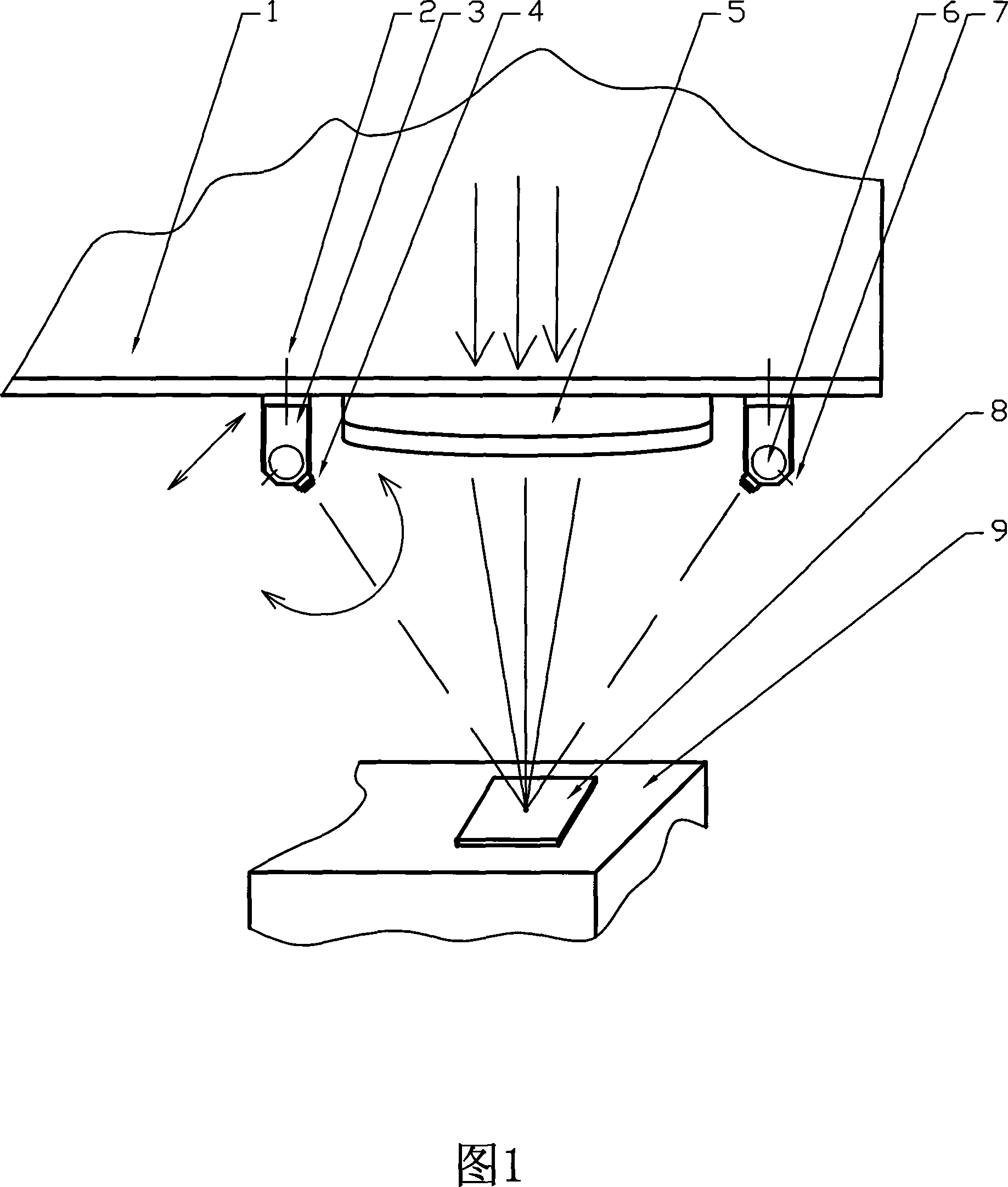
[0014] Figure 1 shows an embodiment of the auxiliary focusing device of the laser marking machine. The laser marking machine includes a laser generator, a focusing mirror 5 fixed on the focusing mirror base 1, a workbench 9 for placing a workpiece 8, and two light pens. Bracket 3, two light pens 4 that can emit visible parallel light beams, and the two light pens 4 are externally connected to a controllable power supply. In this embodiment, the focusing lens base 1 on which the focusing lens 5 is installed is fixed, and the workbench 9 on which the workpiece 8 is placed can be translated up and down.

[0015] Focusing mirror base 1 has threaded holes on both sides of focusing mirror 5, and the threaded holes on both sides are in line with the center of focusing mirror 5. There is a waist-shaped hole on the top of the second bracket 3, and the translation locking screw 2 passes through the waist-shaped hole to connect to focusing mirror base 1. The threaded hole, the support 3 ...


PUM


Abstract

The invention relates to an auxiliary focusing device for laser marking system and the application method; wherein, the device comprises two supports, and two light pens which can give off visible parallel beam and is connected with a controllable power. The supports capable of moving horizontally are arranged on the focus mirror bases at both side of the focus mirror and the two light pens are pivotally arranged on the two supports respectively. Spinning and translating locking devices are arranged on the supports and the side-to-side translation of the supports with the spinning of the light pen can adjust the beam locating on the worktable. The invention adopts the application method that: first regulating and adjusting the distance between the focus mirror and the worktable, which enables the laser beam to focus on the processing workpiece on the worktable and the strongest sparkle serves as the focal point, namely the center of the scanning area, then switching on the light pens and regulate the two beams to overlap on the sparkle on the processing workpiece and lock tightly. The regulation of the distance between the worktable and the focus mirror with the light pens coinciding on the intersection point of the optic axis of the focus mirror and the planar, and focusing and the working counter pointing are both convenient.

Description

(1) Technical field [0001] The invention relates to an auxiliary focusing control device and a use method thereof, in particular to an auxiliary focusing device and a use method of a laser marking machine. (2) Background technology [0002] Laser marking machine is a kind of equipment for marking and processing with laser beam, mainly including laser generator, scanning system, focusing mirror and other related control units. The laser beam enters the focusing mirror after passing through the scanning system, and the parallel incident beam is focused on the focal plane of the focusing mirror, and the focused scanning beam etches the desired pattern on the surface of the workpiece. When the workpiece surface is located on the focal plane of the focusing field lens, the spot diameter is the smallest, the laser energy density is the highest, the etching effect is the finest, and the efficiency is the highest. Therefore, when using a laser marking machine, it is always necessar...

Claims


Application Information

Patent Timeline
IPC IPC(8): B23K26/42B23K26/04B23K26/046B23K26/70
Inventor 吕虹
Owner 深圳市星辰智能控制有限公司
Learn More