
Automatic disconnection device of sewing machine

A technology of automatic cutting and cutting devices, which is applied to sewing machine components, sewing machine thread cutting mechanisms, sewing equipment, etc., can solve the problems of brake damage, power consumption, damage, etc., and achieve the reduction of the overall structure volume and the reduction of the overall structure volume Effect

Inactive Publication Date: 2008-05-07
曾贤长
View PDF0 Cites 0 Cited by
  • Summary
  • Abstract
  • Description
  • Claims
  • Application Information

AI Technical Summary

Problems solved by technology

[0003] 1. The overall structure is complex and bulky: because it uses a linear brake to control the back and forth stroke of the hook body, because the linear stroke of the brake is limited, it must have a swing arm whose force arm is much smaller than the resistance arm. Only by enlarging the stroke of the hooking body can the component meet the back and forth stroke of the hooking body. The area or volume occupied by such a structure must not be effectively reduced due to the length of the swing arm, resulting in a very large overall volume. , it is difficult to meet the current needs of miniaturization and simplification
[0004] 2. The error of linear drive is easy to expand: due to the enlarged stroke of the swing arm, when any part of its component has an error, the error is easily enlarged and accumulated due to the lengthening of the arm, and the hook line body Insufficient or excessive push stroke, causing the hook line body to be unable to tangent or overextrude and damage related components or structures, so there is a need for improvement
[0005] 3. The labor-intensive structure does not meet the economic requirements: because the swing arm is a force-resistance arm that is much larger than the force-applying arm, it is a labor-intensive structure that consumes improper power and is more likely to cause unnecessary damage to the brake, so it is necessary to improve

Method used


Image

  • Automatic disconnection device of sewing machine
  • Automatic disconnection device of sewing machine
  • Automatic disconnection device of sewing machine

Examples


Embodiment Construction

[0035] In order to further understand the structure, characteristics and other purposes of the present invention, the following preferred embodiments are described in detail with accompanying drawings, but the embodiments described in this illustration are for illustration purposes only, not for patent application The only limitation on .

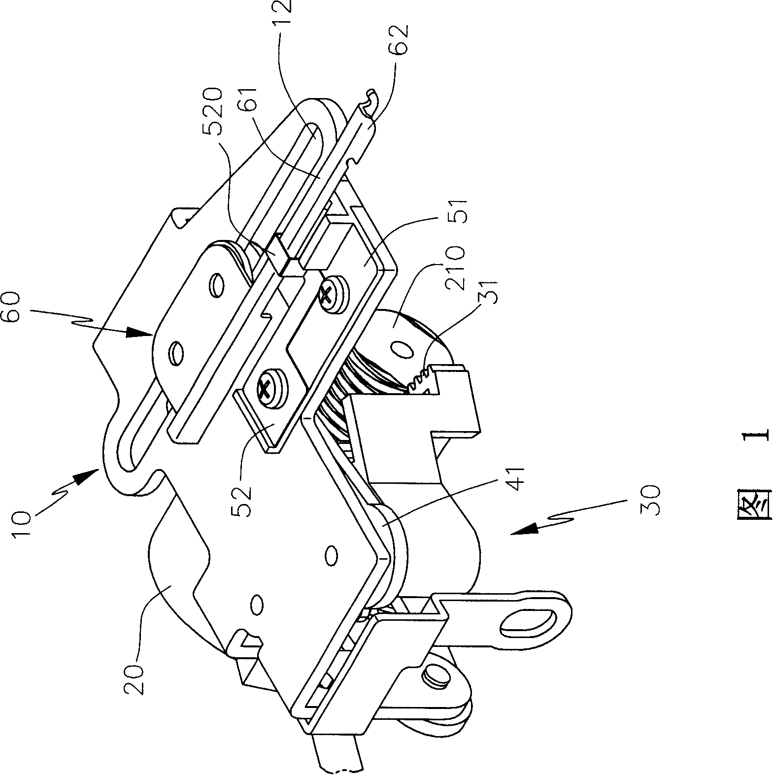
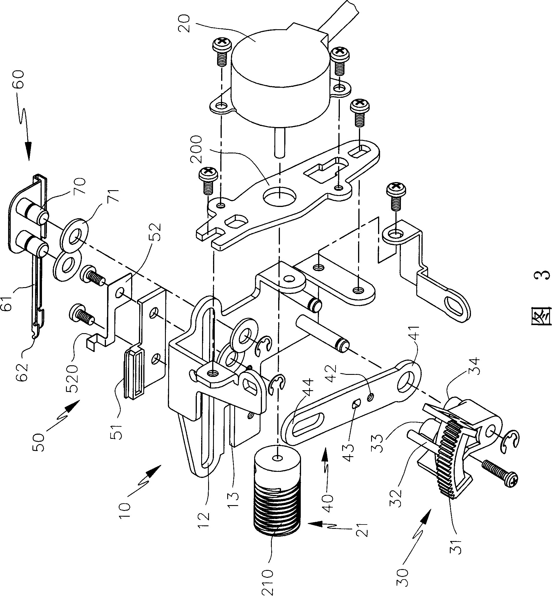
[0036] Please refer to FIG. 1-FIG. 3, the cutting device of the present invention mainly has a main body 10, and the main body 10 is provided with a driving part 21 driven by the driving part 20, and the driving part 21 engages a driven part 30. , the follower 30 coaxially drives a link 40, and one end of the link 40 matches the knife seat 50 of the main body 10 to jointly link and clamp a hook line body 60, and the knife on the knife seat 50 The body 51 performs tangential operation and moves in the direction of the fixed guide structure, so as to achieve overall high stability, high safety and high rationality in structural design and fun...


PUM


Abstract

The invention discloses an automatic cut-off device of the sewing machine, which is an automatic cut-off machine arranged at the passing path of the vehicle suture of the sewing machine, comprising a body. The invention is characterized in that: a structure of a worm shaped drive part driven by a motor shaped driving member is arranged on the body; a driven part with worm teeth is meshed-geared by the drive part; in addition, the driven part actuates a line-loading body; a blade holder with a cutter body is fixed on the body to match with the tangent action of the winding body, so that the integral apparatus can effectively reduce volume to be arranged in the narrow space of the sewing machine, and labor-saving and high speed are achieved.

Description

Technical field: [0001] The invention relates to an automatic cutting device for a sewing machine, especially a cutting device suitable for cutting sewing threads on a sewing machine, which drives a swinging driven part and a linking part through the rotation of the driving part to make the interlocking The parts can be guided in a straight line with the guide structure, and can move quickly to achieve the purpose of controlling, cutting and cutting with high efficiency. Background technique: [0002] At present, there are many patents on the thread tangent structure of the sewing machine, among which, No. 85203813 "Automatic Thread Trimming Device for Flat Car Sewing Machine" and No. 86218218 "Taiwan, China" Improvement of sewing machine thread trimming device for chain stitching", No. 89207548 "Thread trimming drive device for sewing machine", No. 89214516 "Thread trimming device for sewing machine", No. 892 No. 14905 "Improvement of Thread Cutter for Sewing Machine", No....

Claims


Application Information

Patent Timeline
IPC IPC(8): D05B65/00
Inventor 曾贤长
Owner 曾贤长
Learn More