Lower transmission case of mini-tiller

A technology of transmission box and micro-tiller, which is applied in the direction of transmission box, agricultural machinery, agricultural machinery and implements, etc., can solve the problems of poor craftsmanship and high production cost, and achieve the effect of light weight, improved stability and good craftsmanship

Inactive Publication Date: 2015-06-17
CHONGQING JIAXING IND
View PDF1 Cites 0 Cited by
  • Summary
  • Abstract
  • Description
  • Claims
  • Application Information

AI Technical Summary

Problems solved by technology

[0004] Aiming at the problems of poor manufacturability, high cost, and poor stability after installation and connection in the prior art, the present invention provides a lower box body of the micro tillage machine transmission box, which is molded by die-casting , which solves the technical problems of high production cost and poor workmanship of traditional casting technology products. At the same time, the lower box is tightly connected with the middle box through the flange surface, so that the installed transmission box forms a whole, and the stability is good after installation.

Method used


Image

  • Lower transmission case of mini-tiller

Examples


Embodiment Construction

[0013] The present invention will be further described below in conjunction with the accompanying drawings and specific embodiments.

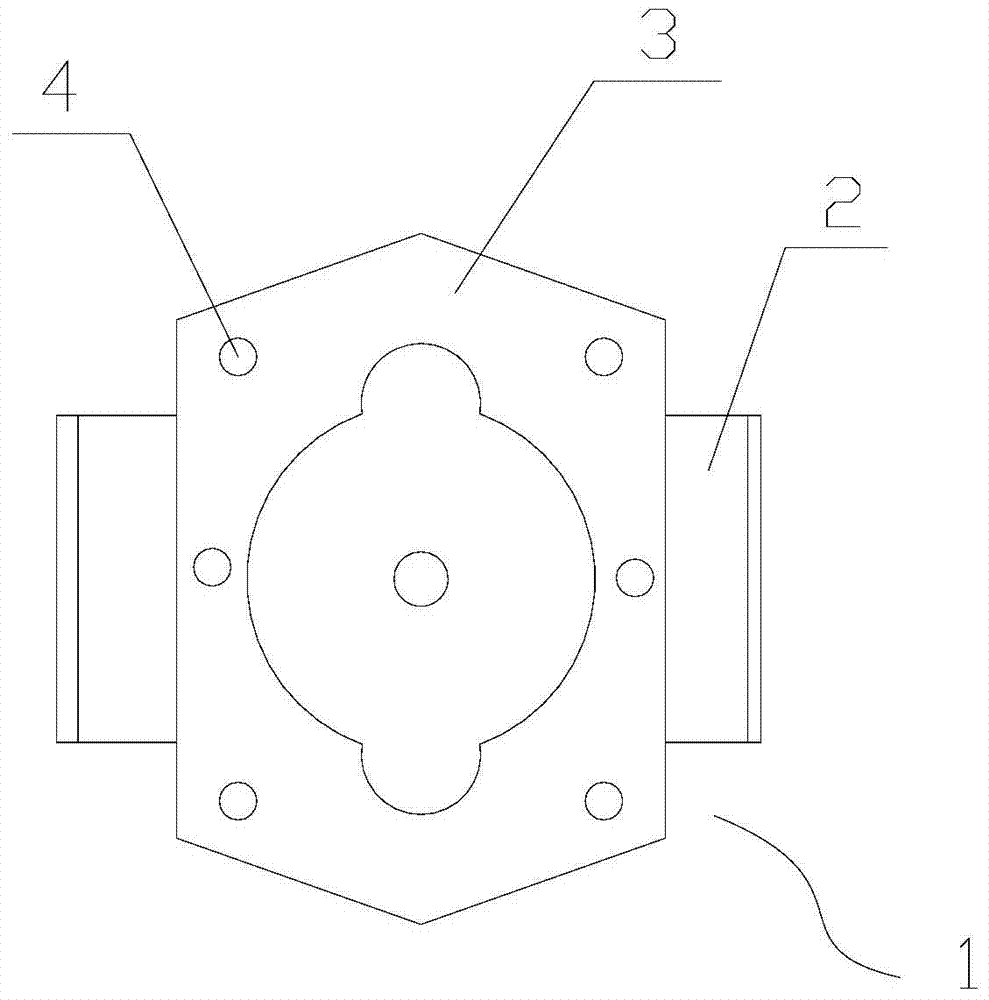
[0014] Such as figure 1 As shown, the lower box of the tiller transmission box includes a box 1, the box 1 is formed by die-casting, the box 1 is a semi-closed structure, and its interior is hollow, and the box 1 is provided for installing the rotary tiller shaft The upper end of the box body 1 is provided with a flange surface 3 connected with the middle box body, and at least six bolt holes 4 are arranged on the flange surface 3 . During installation, the upper end of the box body 1 is connected with the middle box body bolt arranged on the top through the flange surface 3, and the rotary tiller shaft passes through the through hole 2 of the box body 1 and is connected with the transmission part in the middle box body.

[0015] Such as figure 1 As shown, there are six bolt holes 4, which are respectively arranged at the four corners of the ...


PUM


Abstract

A lower transmission case of a mini-tiller comprises a case body, and the case body is formed through pressure casting; the case body is of a semi-closed structure, and the case body is hollow; a transverse through hole for containing a rotary tillage shaft is formed in the case body, and a flange face connected with a middle case body is arranged at the upper end of the case body; and at least six bolt holes are formed in the flange face. A pressure casting forming structure is adopted, and the lower transmission case is good in manufacturability and high in efficiency; and manufacturing cost is reduced, and meanwhile through flange connection, the whole stability after connection of the lower case body and the middle case body is improved.

Description

technical field [0001] The invention belongs to the technical field of agricultural machinery manufacturing, and in particular relates to a lower box body of a transmission box of a tiller. Background technique [0002] The power transmission box is an important part of the transmission mechanism of the tiller. There are couplings, power input shafts and walking shafts installed in the transmission box. The output power of the engine is transmitted to the input shaft in the power transmission box through the coupling. The input shaft transmits power to the rotary tiller shaft below through the vertically arranged travel shaft in the power transmission box, and the tiller is driven by the rotary tiller shaft to rotate. In the prior art, the power transmission box of the micro tillage machine is molded by casting, and it takes a lot of time to cool the mold during manufacture, which makes the whole transmission box poor in manufacturability and high in cost. [0003] On the o...

Claims


Application Information

Patent Timeline
IPC IPC(8): F16H57/02A01B71/06
CPCF16H57/02A01B71/06
Inventor 王德良罗清明
Owner CHONGQING JIAXING IND
Why Eureka
Try Eureka