
Real time on-line safety monitoring system for container crane

A container crane and safety monitoring technology, applied in safety devices, transportation and packaging, load hoisting components, etc., can solve the problems of limited detection parts, expensive testing costs, delayed inspection cycle, etc., to achieve strong applicability and improved economy. And the effect of high safety and reliability

Inactive Publication Date: 2008-05-07
SHANGHAI INTERNATIONAL PORT
View PDF0 Cites 12 Cited by
  • Summary
  • Abstract
  • Description
  • Claims
  • Application Information

AI Technical Summary

Problems solved by technology

[0011] (3) Potential uncertainties caused by model simplification and assumptions in structural overall analysis
[0016] ① Limited detection locations, for example, structural stress detection usually only has 4 to 8 measurement points;
[0017] ② The cost of testing is expensive. For example, the ultrasonic method and magnetic particle flaw detection method are used for structural non-destructive testing. The testing cost of a single crane alone exceeds 10,000 yuan, not including testing auxiliary projects (erecting the testing platform, polishing the surface of the testing area and restoring the paint). etc.) fees;
[0019] ④ The inspection work must be carried out under the non-operating condition of the crane, which will affect the production
When the production shutdown is difficult to arrange, it is easy to cause the delay of the inspection cycle, and even affect the reliability of the inspection data, etc.
[0020] Due to the lack of safety inspection mentioned above, the management and maintenance department lacks a timely and comprehensive grasp and understanding of the status of cranes, especially large cranes.

Method used


Image

  • Real time on-line safety monitoring system for container crane
  • Real time on-line safety monitoring system for container crane

Examples


Embodiment Construction

[0041] Below in conjunction with specific embodiment, further illustrate the present invention. It should be understood that these examples are only used to illustrate the present invention and are not intended to limit the scope of the present invention. In addition, it should be understood that after reading the teachings of the present invention, those skilled in the art can make various changes or modifications to the present invention, and these equivalent forms also fall within the scope defined by the appended claims of the present application.

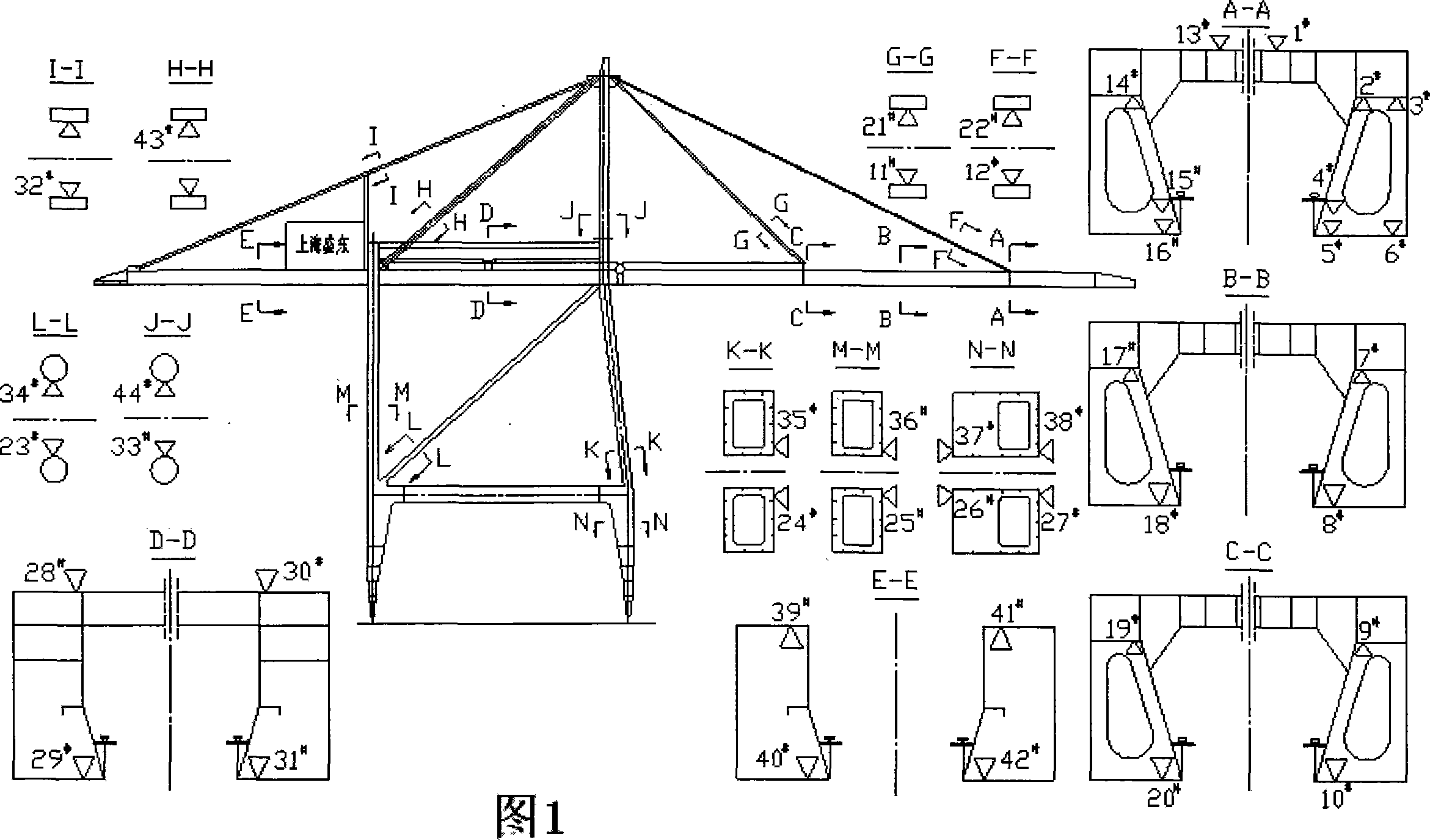
[0042] As shown in Figures 1 and 2, in the real-time online safety monitoring system for container cranes of the present invention, the structural monitoring system connects twelve fiber grating sensors arranged in four parts of the container crane in series to form a four-way transmission system in total. sense network. (The specific four parts are the left side of the outrigger and its tie rod; the right side of the outrigge...


PUM


Abstract

The invention relates to a container crane real time on-line safety monitoring system. Twelve fiber grating sensors are respectively distributed at four parts of a container crane, and connected into one line in series, a four-way fiber is connected with a four optical-fiber cable, the fiber cable accesses signals into a four-channel fiber grating wavelength demodulator in the electric appliance chamber of the container crane, the output signals of the demodulator are inputted into a computer to be processed, and are displayed in a driving cab on the container crane and in a ground technique center monitoring room. The system adopts the high precision, remote, distributed and long lasting fiber grating sensing technique, thus the utilize condition of the structural condition (stress / loading and so on), the safety and fatigue life time and so on ia accurately determined through the real time on-line long-range monitoring to the running condition of the crane, in particular to the structural stress, oscillation and loading (goods and environments) of the crane, thereby providing quantized data for the operation and maintenance of the crane, and improving the economical efficiency and security of the crane.

Description

technical field [0001] The invention relates to a safety monitoring system, in particular to a real-time online safety monitoring system for container cranes. Background technique [0002] At present, with the continuous development of economic globalization and logistics industry, modern port machinery, represented by port container cranes, is increasingly developing in the direction of large-scale, continuous, high-speed, high-efficiency, soft and automatic. On the one hand, these developments have improved production efficiency, saved a lot of energy, and achieved huge social and economic benefits; on the other hand, these developments have also brought some new problems accordingly: [0003] One is that due to the increase in the functions of equipment and systems, the relationship between various operating units has become increasingly complex, resulting in more and more factors affecting equipment safety and work performance; [0004] The second is that the structure ...

Claims


Application Information

Patent Timeline
Patent Type & Authority Applications(China)
IPC IPC(8): B66C13/16B66C15/00
Inventor 包起帆沈沨
Owner SHANGHAI INTERNATIONAL PORT
Learn More