
Power unit for vehicle

A technology for power plants and vehicles, which is applied to control devices, vehicle components, transportation and packaging, etc., can solve the problems of lengthening the front and rear of the vehicle body, and achieve the effect of reducing the number of parts, improving maintainability, and compacting the transmission path.

Active Publication Date: 2008-05-07
HONDA MOTOR CO LTD
View PDF1 Cites 3 Cited by
  • Summary
  • Abstract
  • Description
  • Claims
  • Application Information

AI Technical Summary

Problems solved by technology

[0004] However, in the power plant disclosed in Patent Document 1 above, since the clutch actuator is arranged at the rearmost part of the engine body, the front and rear length of the engine body becomes long. , therefore, there is a tendency that the front and rear lengths of the vehicle body also become longer

Method used


Image

  • Power unit for vehicle
  • Power unit for vehicle
  • Power unit for vehicle

Examples


Embodiment Construction

[0040] Next, embodiments of the present invention will be described based on embodiments of the present invention shown in the drawings.

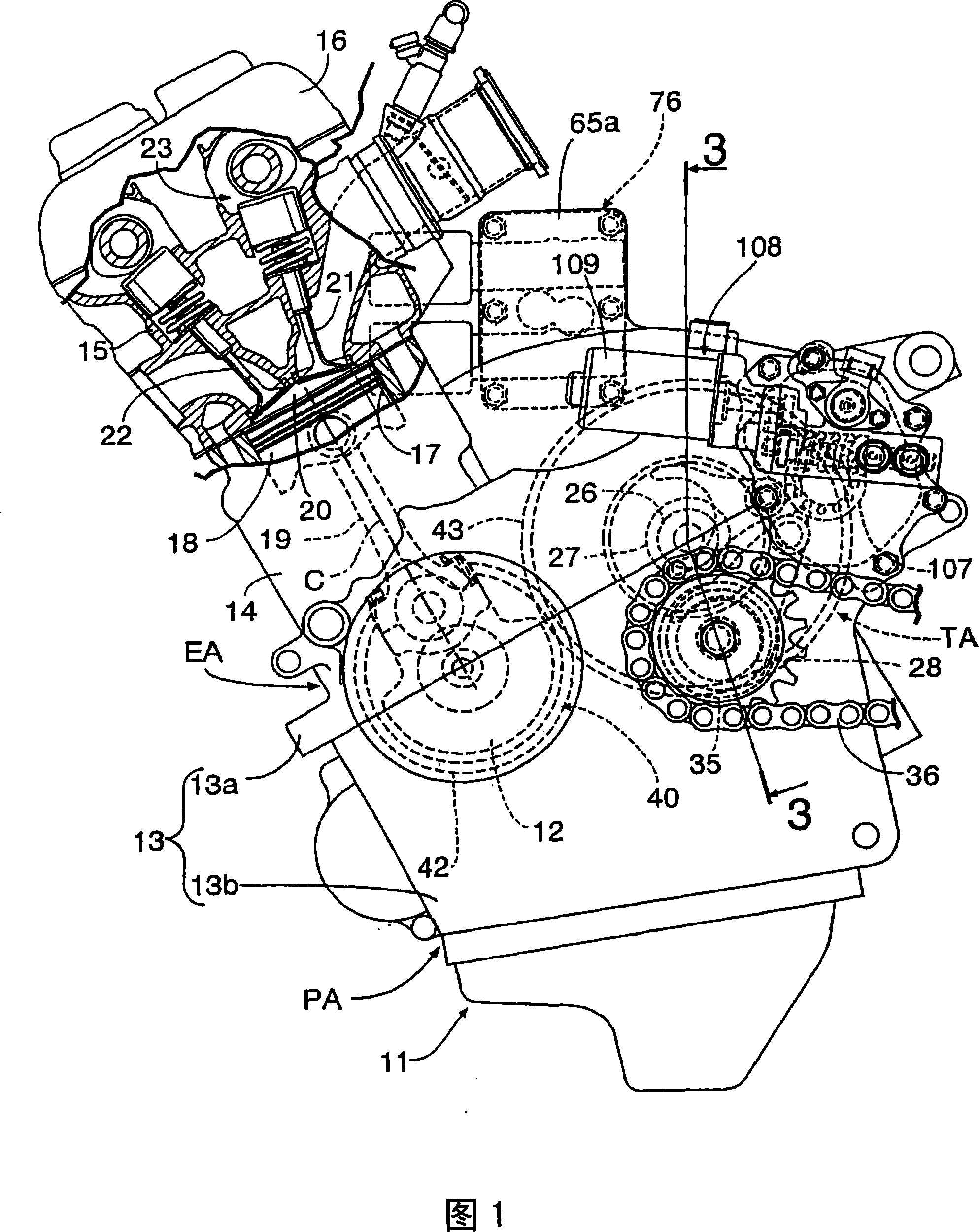
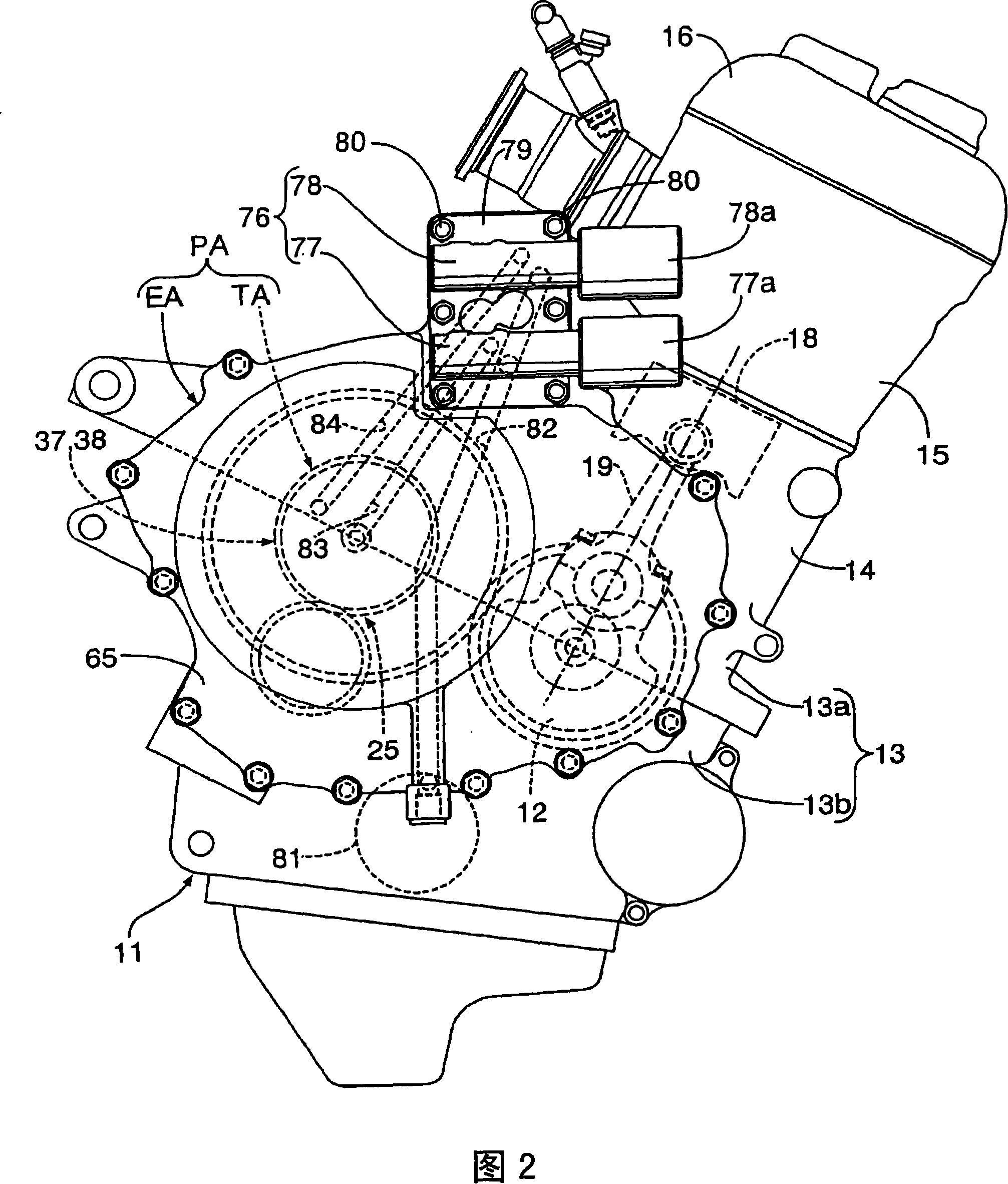
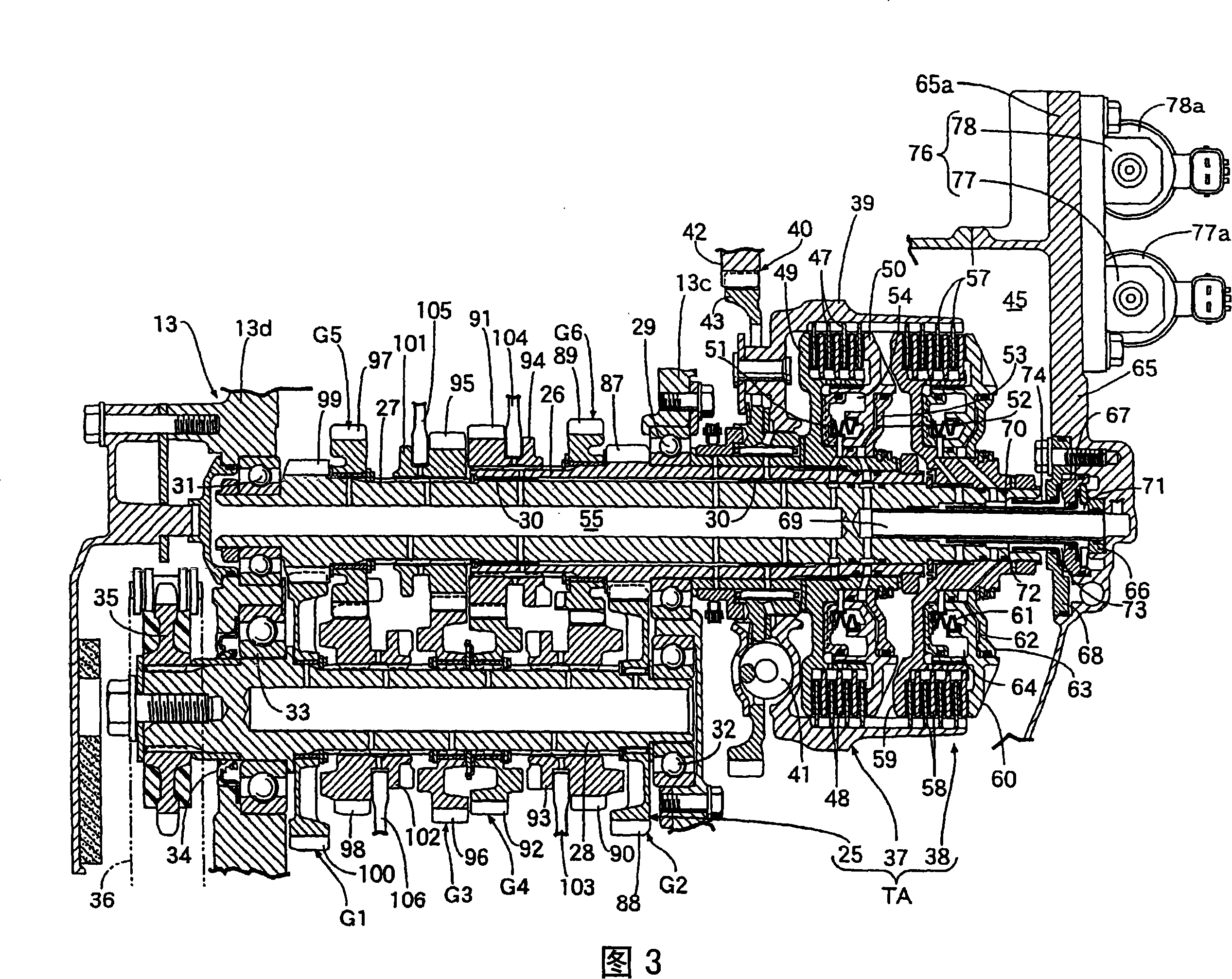
[0041] Fig. 1~Fig. 4 is the figure that shows the first embodiment of the present invention, and Fig. 1 is the left side view of the power plant of the first embodiment, Fig. 2 is the right side view of power plant, Fig. 3 is the power plant of Fig. 1 3-3 line sectional view, Fig. 4 is an enlarged view of the main part of Fig. 3 .

[0042] First, in FIGS. 1 and 2 , the power unit PA is composed of an engine EA and a transmission TA for changing the power of the engine EA, and is mounted on a vehicle such as a motorcycle. The engine main body 11 of the above-mentioned engine EA includes: a crankcase 13 that rotatably supports a crankshaft 12 along the left-right direction of the motorcycle; A cylinder block 14 having a cylinder bore 17 and combined with a clutch cover 13; a cylinder head 15 formed between the cylinder block 14 and a combust...


PUM


Abstract

The present invention provides a power unit for a vehicle, which structure is that clutches for switching between the connection and disconnection of the transmission of power are provided in a power transmission path for transmitting a rotational drive force of a crankshaft to a drive wheel. A clutch cover is joined to a side portion of a crankcase. A clutch chamber for accommodating the clutches is formed between the crankcase and the clutch cover. A clutch actuator for controlling the switching between an engaged condition and disengaged condition of the clutches is mounted on an engine body. The clutch actuator (76) is provided on an upper portion of the clutch cover (65).

Description

technical field [0001] The present invention relates to a power plant for a vehicle, which is provided with a clutch capable of switching power transmission on / off in the middle of a power transmission path that transmits the rotational power of a crankshaft rotatably supported by a crankcase to drive wheels, and on an engine body. A clutch actuator that controls the above-mentioned clutch cut-off / engage switching is installed on the top. Background technique [0002] Such a power plant for a vehicle is disclosed, for example, in Patent Document 1 or the like. [0003] Patent Document 1: Japanese Patent Application Laid-Open No. 11-222043 [0004] However, in the power plant disclosed in Patent Document 1, since the clutch actuator is arranged at the rearmost part of the engine body, the front-to-rear length of the engine body tends to be longer, and therefore the front-to-rear length of the vehicle body tends to be longer. Contents of the invention [0005] The present ...

Claims


Application Information

Patent Timeline
Patent Type & Authority Applications(China)
IPC IPC(8): B60K17/02F02B39/12
CPCF16D25/0638F16D25/10F16D21/06
Inventor 小笠原敦
Owner HONDA MOTOR CO LTD
Learn More