Secondary battery

A technology for secondary batteries and battery boxes, which is applied to battery pack components, battery covers/end covers, battery boxes/coatings, etc. It can solve the problems of reduced strength of insulating rings, reduced impact resistance, and dissipation, so as to ensure total Area, breakage prevention, high heat dissipation effect

Inactive Publication Date: 2010-04-21
PANASONIC CORP
View PDF6 Cites 0 Cited by
  • Summary
  • Abstract
  • Description
  • Claims
  • Application Information

AI Technical Summary

Problems solved by technology

[0009] So, for Figure 9 , Figure 10 For the secondary battery with the structure shown, in the case of impact, such as Figure 11 As shown, sometimes the pole plate group 33 will move towards the assembly sealing plate 35 under the action of impact. In this case, there is the following problem: the insulating plate 36a on the side of the assembly sealing plate 35 is deformed under the impact force, forming The vent hole 38 on the filter 37 of the sealing plate 35 is blocked by the insulating plate 36a, and there is a possibility that the generated gas cannot be dissipated.
[0010] On the other hand, with the structure of the battery disclosed in Patent Document 2, the movement of the plate group when receiving an impact is prevented to prevent the deformation of the lead wire, but due to the arrangement of the insulating ring, there is gas from the outer peripheral portion of the plate group. The problem that the exhaust path is damaged, if the insulating ring is notched to ensure the exhaust path, the strength of the insulating ring made of resin will be reduced, and the impact resistance effect will be reduced.
[0011] In addition, in the structure of the battery disclosed in Patent Document 3, the gas discharge path is ensured by providing a protrusion on the periphery of the vent hole of the metal sealing plate, but there is a problem that the movement of the electrode group when receiving an impact cannot be prevented. The problem, in addition, if the protrusion is increased to prevent movement, there is a problem that it will directly contact the plate group and cause a short circuit

Method used


Image

  • Secondary battery
  • Secondary battery
  • Secondary battery

Examples


Embodiment Construction

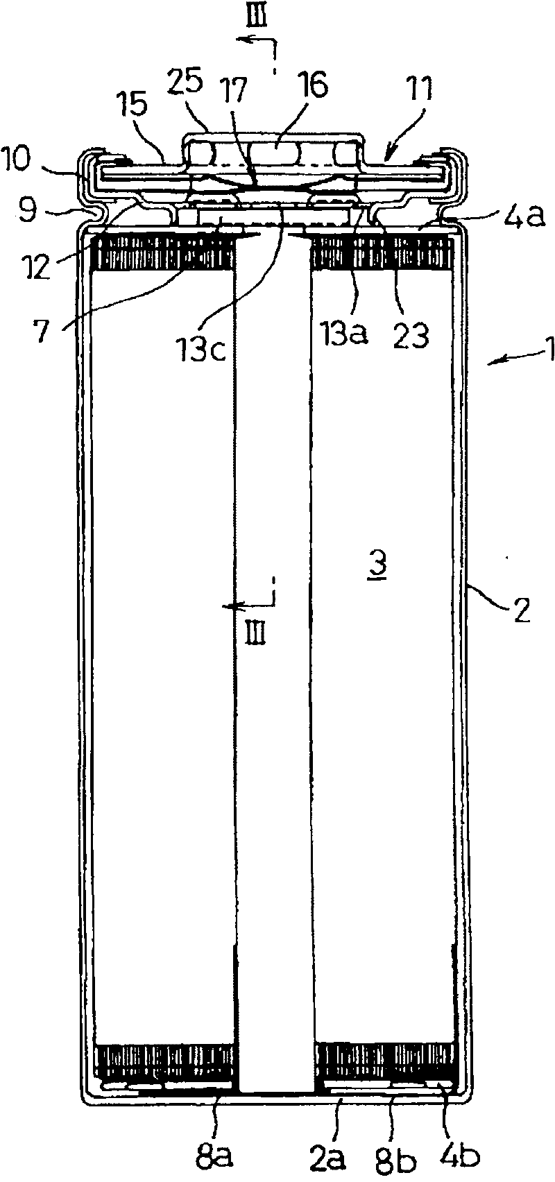
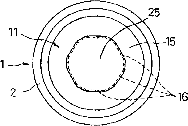
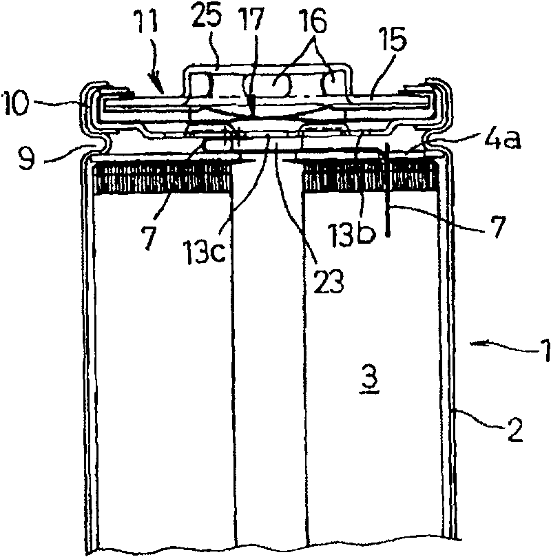
[0034] Below, refer to Figure 1 ~ Figure 8B One embodiment of the secondary battery of the present invention will be described.

[0035] exist Figure 1 ~ Figure 3 Among them, 1 is a cylindrical secondary battery composed of a lithium ion battery, and an electrode plate group 3 serving as a power generating element is accommodated together with an electrolytic solution in a bottomed cylindrical battery case 2 . The electrode plate group 3 is formed by winding the strip-shaped positive electrode plate, separator, negative electrode plate, and separator on the outer periphery of the winding core member in a state of being stacked in sequence, and pulling out the winding core member after the winding is completed. It is a structure in which a positive electrode plate and a negative electrode plate are stacked with a separator interposed therebetween. The separator protrudes upward and downward with an appropriate size from the positive electrode plate and the negative electrod...


PUM


Abstract

A secondary battery (1) where an electrode plate group (3) and an electrolyte are received in a battery case (2) and one end opening of the battery case (2) is sealed with an assembly seal plate (11)integral with a safety mechanism (17). When the inside of the battery case (2) is higher than or equal to a predetermined pressure, the safety mechanism (17) discharges the pressure to the outside. Atleast a part (13a) of ventilation holes (13a, 13b, 13c), which face the inside of the battery case (2), of the assembly seal plate (11) is formed as an opening by forming a cut and bent-up section (23), the tip of the cut and bent-up section (23) is made to be in contact with an insulation plate (4a) provided so as to be in contact with one end of the electrode plate group (3), and thereby the movement of the electrode plate group (3) is restrained. This prevents occurrence of a failure caused by movement of the electrode group (3) when the secondary battery is subjected to an impact or vibration.

Description

technical field [0001] The present invention relates to a secondary battery, and more particularly, to a secondary battery that prevents malfunctions caused by movement of electrode plate groups due to impact and vibration, and improves impact resistance. Background technique [0002] As secondary batteries such as lithium-ion batteries and nickel-metal hydride batteries, secondary batteries 31 having the following structure are known: Figure 9 As shown, in a bottomed cylindrical battery case 32, the electrode plate group 33 and the electrolyte solution as the power generation elements are accommodated, and the opening of the battery case 32 is sealed with an assembly sealing plate 35 through an insulating gasket 34, and the secondary electrodes are sealed. The lead wire (not shown) of a kind of polarity that one end of plate group 33 extends is connected on the assembly sealing plate 35, the lead wire (not shown) of another kind of polarity that extends from the other end o...

Claims


Application Information

Patent Timeline
Patent Type & Authority Patents(China)
IPC IPC(8): H01M2/12H01M2/04H01M2/26H01M50/536H01M50/538
CPCH01M2/1229H01M2/263H01M2/0225Y02E60/12Y02E60/10H01M50/56H01M50/325H01M50/538H01M50/536H01M50/30H01M50/147
Inventor 桥本达也井上广树神月清美平川靖
Owner PANASONIC CORP
Why Eureka
Try Eureka