
Measurement mechanism and measurement method of ferroelectric materials electric hysteresis loop wire

A technology of hysteresis loops and ferroelectric materials, which is applied in measuring devices, hysteresis curve measurement, and electrical variable measurement, can solve problems such as inability to compare and analyze, and achieve the effect of ensuring accuracy

Inactive Publication Date: 2008-04-09
XI AN JIAOTONG UNIV
View PDF2 Cites 34 Cited by
  • Summary
  • Abstract
  • Description
  • Claims
  • Application Information

AI Technical Summary

Problems solved by technology

Due to the differences in measurement methods and equipment used, the above-mentioned prior art cannot quantitatively compare the differential permittivity obtained by P-E with the reversible permittivity obtained by the LCR instrument

Method used


Image

  • Measurement mechanism and measurement method of ferroelectric materials electric hysteresis loop wire
  • Measurement mechanism and measurement method of ferroelectric materials electric hysteresis loop wire
  • Measurement mechanism and measurement method of ferroelectric materials electric hysteresis loop wire

Examples


example 1

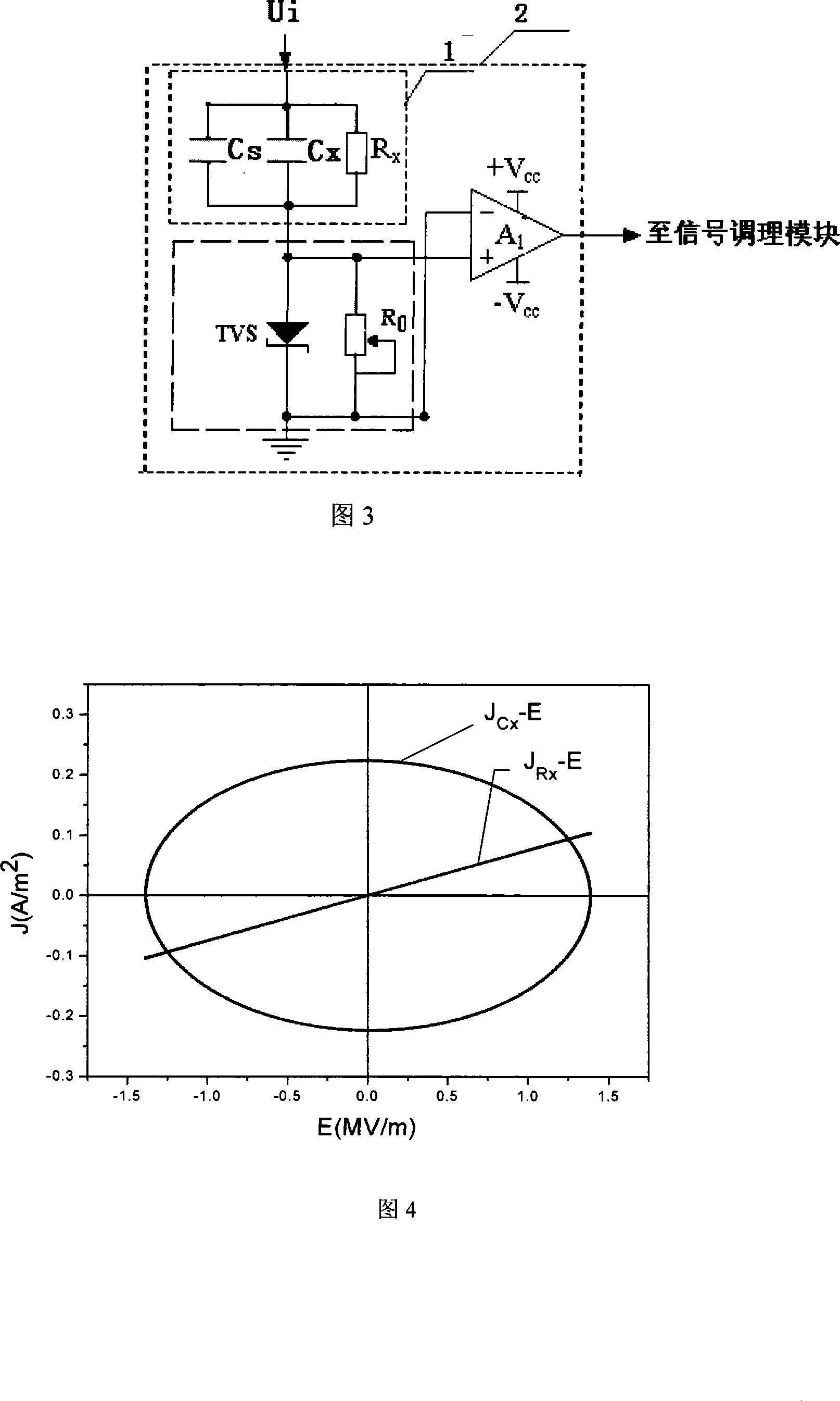
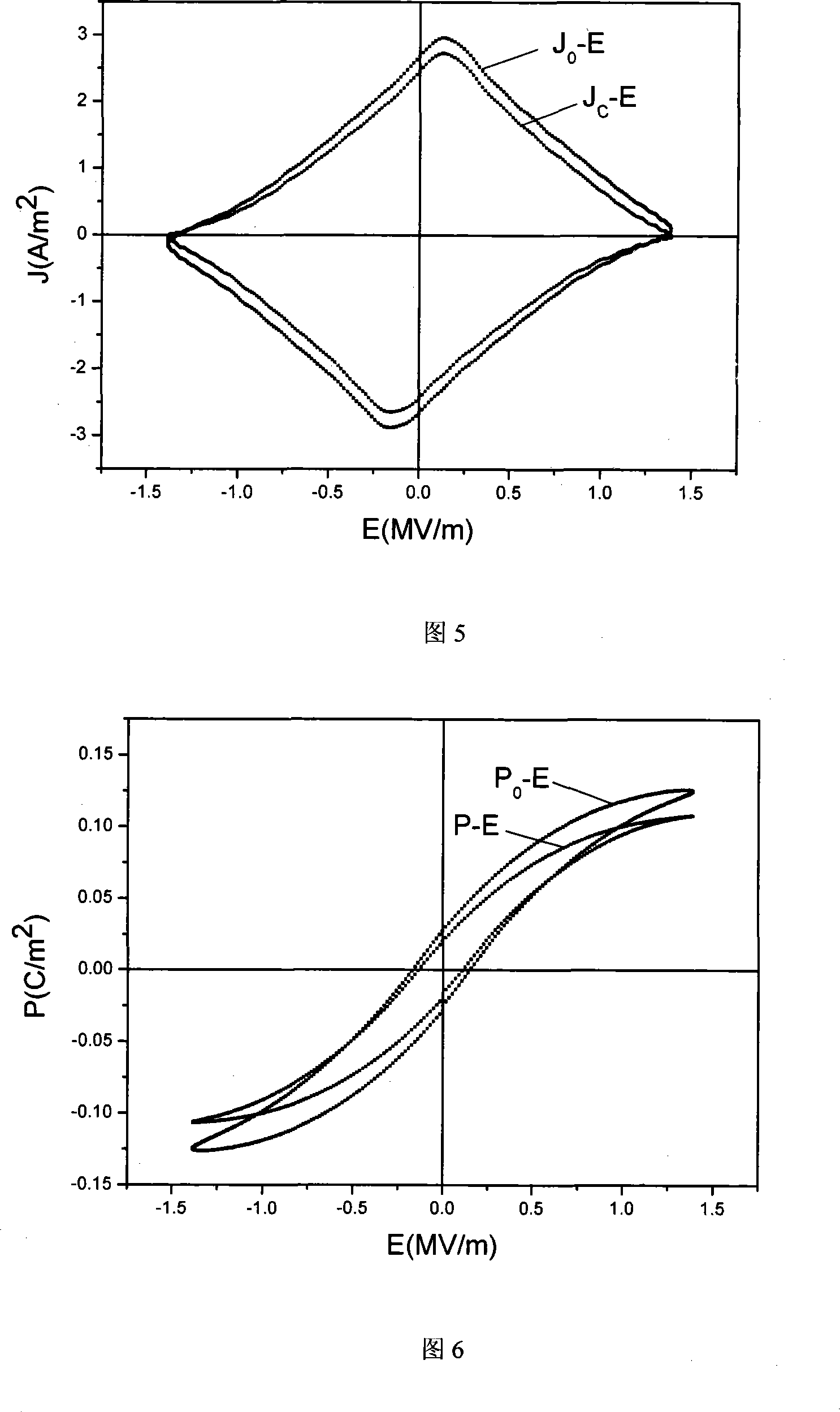
[0049] Test sample 1 is a ferroelectric ceramic Ba 0.9 Sr 0.1 TiO 3 , sample thickness d=9.8×10 -4 m, electrode area S=7.329×10 -5 m 2 , the sinusoidal excitation voltage U i The amplitude is 1800V, the frequency is 1Hz, measured according to step a of the aforementioned method, the J-E relationship curve and the P-E relationship curve are obtained, and the coercive field strength E c , the remanent polarization P r , the spontaneous polarization P s , the maximum polarization P max . In this example, the leakage conduction resistance R x =1.677×10 8 Ω, linearly polarized capacitance C x =2.028nF, loss current density J Rx , Linear polarization current density J Cx The relationship curve J with the electric field intensity E Rx -E and J Cx -E As shown in Figure 4, the current density J before and after compensation 0 and J C The relationship curve J with the electric field intensity E 0 -E and J C -E As shown in Figure 5, the polarization strength P before a...

example 2

[0056] Test sample 1 is ferroelectric ceramic BaTi 0.9 sn 0.1 o 3 , sample thickness d=1.0×10 -3 m, electrode area S=7.329×10 -5 m 2 , after adding a DC bias voltage of 1500V to the test sample 1 for 60 seconds, superimpose a sinusoidal alternating signal with a frequency of 1Hz and an amplitude of 10V. The resulting P-E curve is shown in Figure 7. The reversible dielectric constant of test sample 1 was calculated to be 4092. It can be seen from Figure 7 that the upper and lower branches of the curve coincide and form a linear relationship, and an accurate and reliable reversible permittivity is obtained.


PUM

PropertyMeasurementUnit
Thicknessaaaaaaaaaa
Electrode areaaaaaaaaaaa
Amplitudeaaaaaaaaaa

Abstract

The invention discloses an apparatus for measuring the ferroelectric hysteresis of ferroelectric materials which is based on a current measurement circuit, as well as a measurement method thereof. The invention inputs a simulated output signal generated by a computer processing unit into a high voltage amplifier through a signal source and a data acquisition board, thus giving excitation voltage to a sample being tested, and then through a sampling resistance R0, sampled current signal is input into a signal regulating module through an operational amplifier, and then the sampled current signal is transmitted back into the computer processing unit through the data acquisition board. By separating the current signal acquired from the measurement into three parts as linear polarization, non-linear polarization and electric loss, the measurement system is provided with not only the function of measuring the P-E relationship, but also the function of acquiring the relationship between the real spontaneous polarization and induced polarization of the dielectric substance being tested and the field intensity. Furthermore, by superimposing actuating signal of a small alternative electric field to a bias electric field with constant intensity and synchronously collecting the corresponding change information of the polarization intensity of the sample being tested, then the reversible permittivity can be acquired.

Description

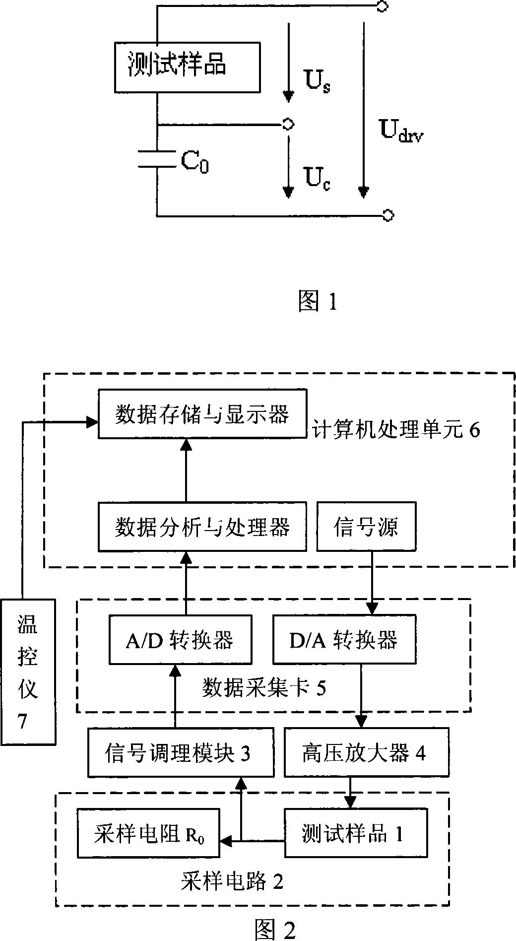
technical field [0001] The invention relates to a measuring device and a measuring method for hysteresis loops of ferroelectric materials. Background technique [0002] The hysteresis loop is an important characteristic and basic criterion of ferroelectrics. The Sawyer-Tower circuit (see Figure 1) is the most widely used hysteresis loop test circuit at present. In the hysteresis loop measurement method based on this, the test sample and the sampling capacitor C 0 in series, the sampling capacitor C 0 Equivalent to the role of an integrator, the current flowing through the sample is integrated on it to form a charge, and the voltage U is displayed by the oscilloscope 0 with excitation voltage U drv The relationship curve is the relationship curve between the electric hysteresis loop polarization P and the electric field intensity E. Due to the leakage conductance R in the ferroelectric material x , dielectric loss and linear capacitance C x Equivalent effect, when measu...

Claims


Application Information

Patent Timeline
IPC IPC(8): G01R33/12G01R33/14G01R19/00G01R19/08G01R29/12G01R27/26
Inventor 罗平生王亦春王晓莉徐华陆彬
Owner XI AN JIAOTONG UNIV
Learn More