
Sample bench

A technology of sample stage and object stage, which is applied to the field of sample stage for cross-sectional analysis of focused particle beams, can solve problems such as gap defects, and achieve the effect of improving accuracy

Inactive Publication Date: 2008-04-02
SEMICON MFG INT (SHANGHAI) CORP
View PDF1 Cites 6 Cited by
  • Summary
  • Abstract
  • Description
  • Claims
  • Application Information

AI Technical Summary

Problems solved by technology

[0005] The invention provides a sample stage for focused ion beam section analysis to solve the problem of gap defects when using focused ion beam to prepare sample sections on the existing sample stage

Method used


Image

  • Sample bench
  • Sample bench
  • Sample bench

Examples


Embodiment Construction

[0037] In order to make the above objects, features and advantages of the present invention more comprehensible, specific implementations of the present invention will be described in detail below in conjunction with the accompanying drawings.

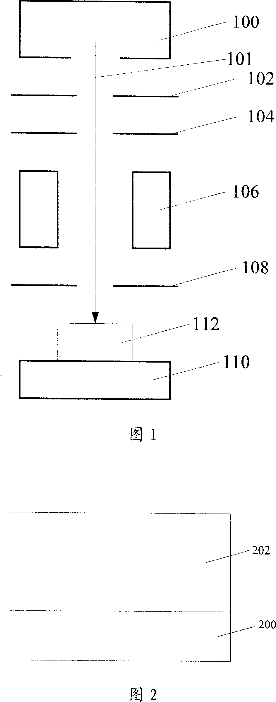
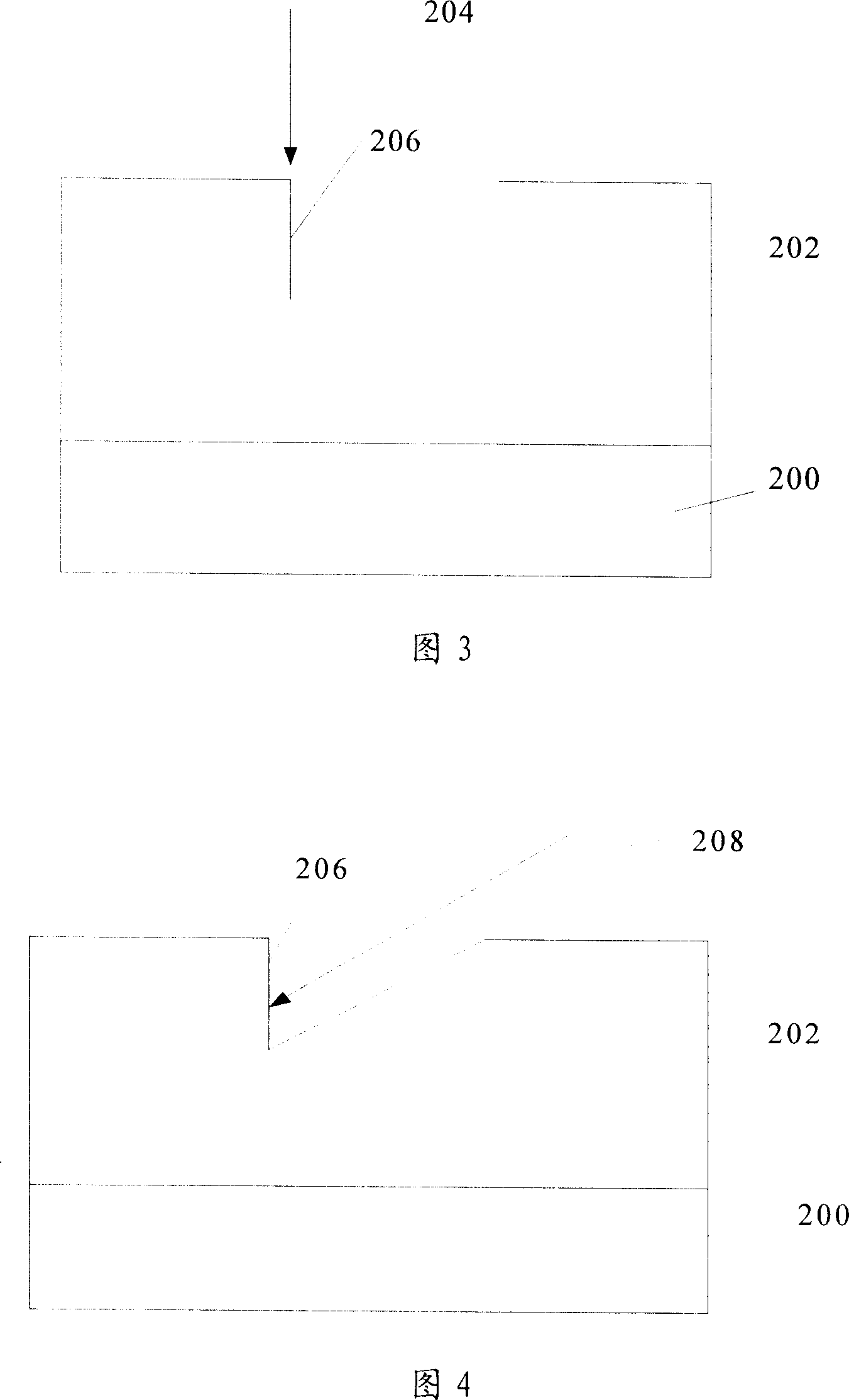
[0038] The focused ion beam (Focused Ion Beam, FIB) will generate ions (mainly Ga + ) after being accelerated by an electron lens and focused on the surface of the chip sample, the high-energy and high-speed ions can remove the surface material of the chip to generate a cross section, which is assisted by a scanning electron microscope to observe the internal conditions of the chip, such as defects. To analyze the defects of the sample by using the focused ion beam, first place the thin slice of the sample on the sample stage, and then place the sample stage under the focused ion beam. The existing technology is limited by the plane surface of the sample stage. After the sample is placed on the sample stage, the ion beam can only hit t...


PUM


Abstract

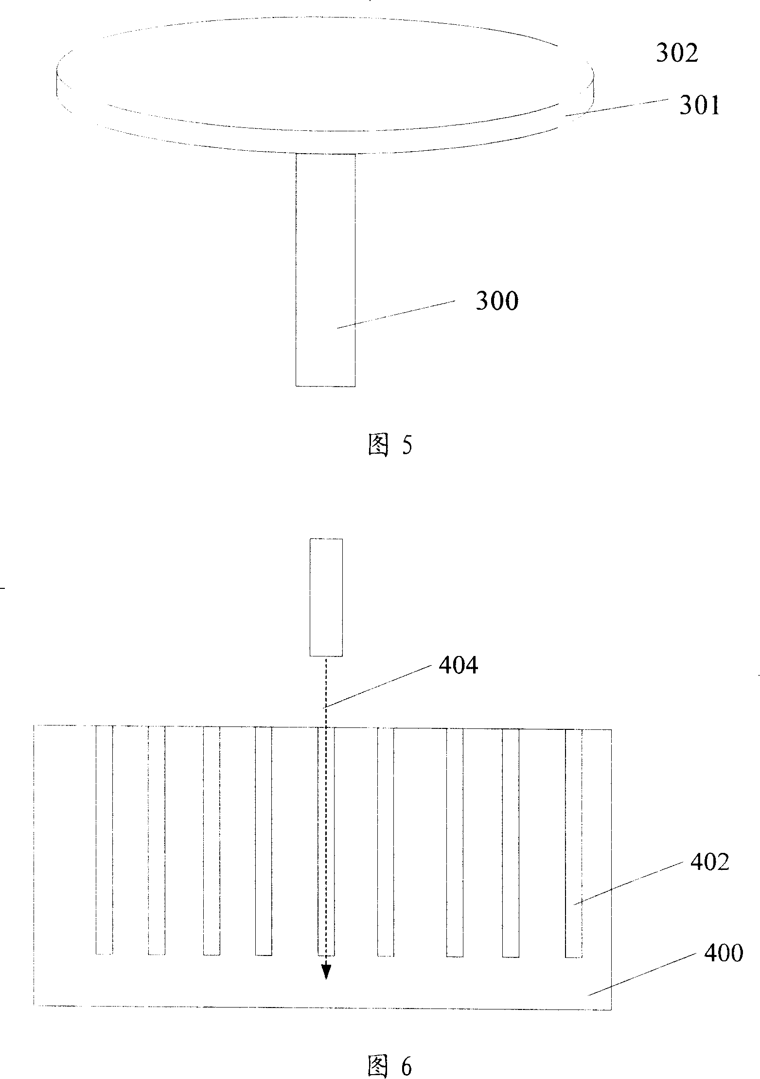
A sample table used in section analysis of focused ion beam comprises a support bar and an object stage, wherein, the object stage comprises a first carrying surface connected with the support bar. The invention is characterized in that the object stage also comprises at least one second carrying surface intersected with the first carrying surface. The object stage can be used in section analysis equipment of focused ion beam for preparing an inclined section.

Description

technical field [0001] The invention relates to the technical field of semiconductor manufacturing, in particular to a sample stage for section analysis of focused particle beams. Background technique [0002] A focused ion beam (Focused Ion Beam, FIB) can be used to analyze the cross section of an integrated circuit chip, so as to observe and determine defects in the chip. Its main principle is: the ions (mainly Jia Ga) generated by the ion source + ) after acceleration, the electron lens is used to focus, and the high-energy and high-speed ions hit the designated position on the chip, and the surface material of the chip is removed to generate a cross section, which is assisted by a scanning electron microscope (SEM) to observe defects in each fault in the chip. Chinese patent application number 99102770.1 discloses a FIB device. As shown in Fig. 1, described FIB equipment generally comprises ion source 100, ion beam extraction electrode 102, electrostatic lens 104, defl...

Claims


Application Information

Patent Timeline
IPC IPC(8): G01N23/18G01N13/10H01J37/26H01L21/66
Inventor 赖李龙
Owner SEMICON MFG INT (SHANGHAI) CORP
Learn More