
Radiator

A technology of radiator and heat dissipation area, applied in the direction of instruments, instrument cooling, electric solid devices, etc., can solve the problems of reducing the heat dissipation effect of the radiator 100, and achieve the effect of low impact and utilization of heat dissipation space

Inactive Publication Date: 2010-04-21
SHENZHEN FLUENCE TECH
View PDF2 Cites 0 Cited by
  • Summary
  • Abstract
  • Description
  • Claims
  • Application Information

AI Technical Summary

Problems solved by technology

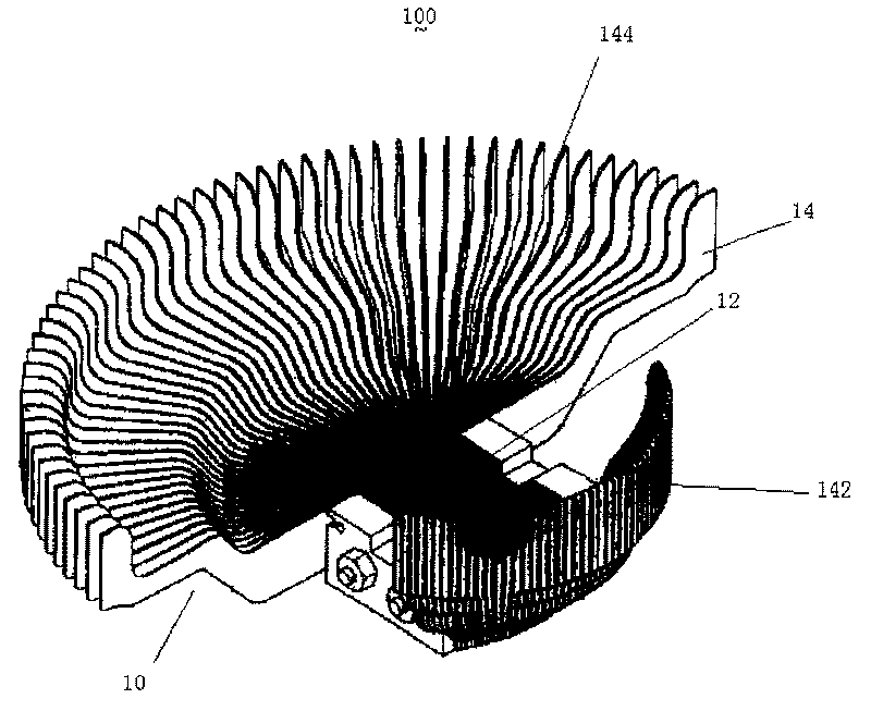
[0004] But the heat sink 100 of this kind of structure still has certain defects, and its long heat dissipation area 144 and short heat dissipation area 142 are matching structures, and every time a long heat dissipation area 144 is increased or decreased, a short heat dissipation area 142 must be correspondingly increased or decreased. , in practical applications, the position of the heat source on the circuit board is various, and the long heat dissipation area 144 or the short heat dissipation area 142 are required to be used together, and the heat sink 100 of this structure does not have corresponding characteristics. When the area of ​​the heat dissipation area 142 is increased, the long heat dissipation area 144 is also correspondingly reduced, thereby reducing the heat dissipation effect of the radiator 100

Method used


Image

  • Radiator
  • Radiator
  • Radiator

Examples


Embodiment Construction

[0024] The present invention will be further described below in conjunction with drawings and embodiments.

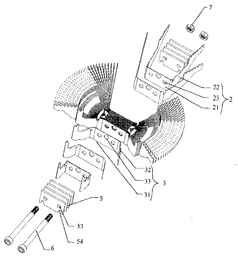
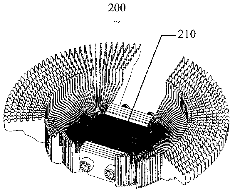
[0025] Please refer to figure 2 ~Figure 8, figure 2 It is a schematic diagram of the decomposition structure of the radiator of the present invention; image 3 is a schematic structural view of the radiator of the present invention; Figure 4 It is a schematic diagram of the overall structure of the combination of the radiator of the present invention and the device to be dissipated; Figure 5 It is a schematic structural diagram of a further improved embodiment of the radiator of the present invention; Figure 6 yes Figure 5 Schematic diagram of the breakdown structure; Figure 7 yes Figure 6 The enlarged structure diagram of the through hole 83 and the screw 87. The radiator 200 includes a main heat sink 2 , a secondary heat sink 3 , an extruded block 5 , bolts 6 , nuts 7 and a connecting seat 8 . The main heat sink 2 includes a heat absorption area 21 and...


PUM


Abstract

The invention relates to a radiator, comprising a plurality of radiating fins include a heat absorption area and a radiating area connected with the heat absorption area and arranged at two sides thereof, the heat absorption area is overlaped to form a heat absorption module of the radiator, the radiating area is dispersed outward along the heat absorption module and radiate the heat absorbed fromthe heat absorption module, wherein, the radiating fins are divided into main radiating fins and auxiliary radiating fins, the radiating area of main radiating fins is larger than that of auxiliary radiating fins. The radiator of the invention has good radiating effect and changes the shape according to practical application, utilizes the radiating space effetively to get optimization of radiatingeffect.

Description

【Technical field】 [0001] The invention relates to the field of radiators for computers, in particular to a radiator whose heat dissipation area can be changed according to actual needs. 【Background technique】 [0002] Some electronic components such as the central processing unit and graphics card will generate a lot of heat during work. If the heat is not dissipated in time, the stability of the electronic components will be affected, thereby reducing their service life. The heat sink emerges as the times require, which can absorb the heat generated by electronic components during work, and prevent electronic components from overheating and causing unstable performance. [0003] Please refer to figure 1 , is a structural diagram of a heat sink in the prior art, which is a Chinese patent application with application number 200510103968.8. The heat sink 100 includes a plurality of sheet-shaped heat sinks 10 stacked on top of each other, and each heat sink 10 includes A heat...

Claims


Application Information

Patent Timeline
Patent Type & Authority Patents(China)
IPC IPC(8): H05K7/20H01L23/34G06F1/20G12B15/06
Inventor 杜建军
Owner SHENZHEN FLUENCE TECH
Learn More