
Differential speed reducer and brushless motor with same

A technology of brushless motors and reducers, which is applied in the direction of electrical components, electromechanical devices, electric components, etc., can solve the problem of small reduction ratio range of the two-stage reducer, and achieve improved transmission efficiency, compact motor structure, and high reduction ratio. Effect

Inactive Publication Date: 2022-03-01
北京动思创新科技有限公司
View PDF7 Cites 0 Cited by
  • Summary
  • Abstract
  • Description
  • Claims
  • Application Information

AI Technical Summary

Problems solved by technology

[0005] The purpose of the present invention is to provide a differential reducer and a brushless motor with the reducer, so as to solve the technical problem of the two-stage reducer with a small reduction ratio range in the prior art

Method used


Image

  • Differential speed reducer and brushless motor with same
  • Differential speed reducer and brushless motor with same
  • Differential speed reducer and brushless motor with same

Examples


Embodiment Construction

[0039] In order to make the purpose, technical solution and advantages of the present invention clearer, the technical solution of the present invention will be described in detail below. Apparently, the described embodiments are only some of the embodiments of the present invention, but not all of them. Based on the embodiments of the present invention, all other implementations obtained by persons of ordinary skill in the art without making creative efforts fall within the protection scope of the present invention.

[0040]In describing the present invention, it should be understood that the terms "center", "longitudinal", "transverse", "length", "width", "thickness", "upper", "lower", "front", " Orientation indicated by rear, left, right, vertical, horizontal, top, bottom, inside, outside, clockwise, counterclockwise, etc. The positional relationship is based on the orientation or positional relationship shown in the drawings, and is only for the convenience of describing ...


PUM


Abstract

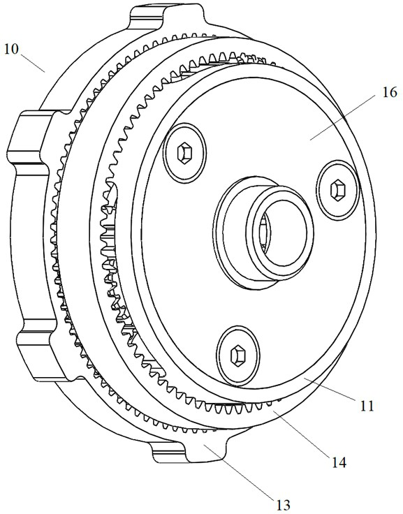
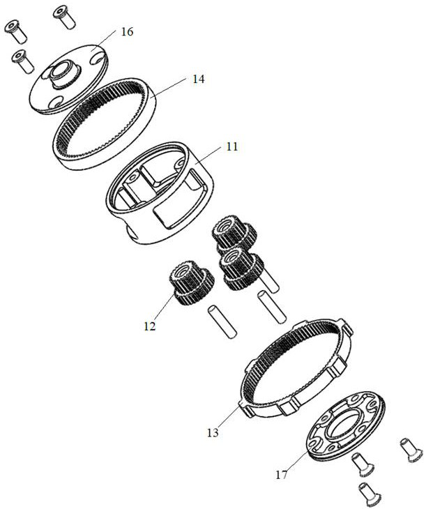
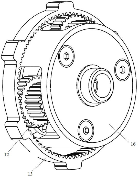
The invention provides a differential speed reducer and a brushless motor with the same, relates to the technical field of speed reducers, and mainly aims to provide a lightweight speed reducer structure with a large reduction ratio range. The differential speed reducer comprises a reduction gearbox frame and a driving part, the reduction gearbox frame is of a hollow annular structure, tower type planet wheels are arranged in the reduction gearbox frame, the number of the tower type planet wheels is at least two, at least two layers of gears with different diameters are distributed on any tower type planet wheel in the axis direction of the tower type planet wheel, and the sizes of the gears located on the same layer are consistent; a fixed gear ring and a movable gear ring are arranged on the periphery of the reduction gearbox frame in a sleeved mode, the fixed gear ring is fixedly arranged, and the fixed gear ring and the movable gear ring are meshed with the gears located on the different layers respectively. The peripheral side of the driving part is sleeved with a sun gear, and the sun gear is meshed with gears on a certain layer of all the tower type planet gears. When the driving part rotates, the tower type planet gear can rotate along the inner side wall of the fixed gear ring under the driving of the sun gear and drive the movable gear ring to rotate.

Description

technical field [0001] The invention relates to the technical field of reducers, in particular to a differential reducer and a brushless motor with the reducer. Background technique [0002] In the industrial field, the reducer plays the role of matching speed and transmitting torque between the prime mover and the working machine or actuator. The planetary reducer has been widely used in the industrial field because of its light weight, small size, large transmission ratio range, high efficiency, stable operation, low noise and strong adaptability. The planetary reducer is composed of a planetary gear, a sun gear, and an inner ring gear. The planetary gear rotates around the sun gear in the inner ring gear, decelerates the high-speed rotation of the sun gear, and outputs it through the gearbox frame. In practical application, the magnetic steel, stator coil, sun gear, planetary gear, ring gear, gearbox frame and other key components are mostly used. After the motor is ene...

Claims


Application Information

Patent Timeline
IPC IPC(8): H02K7/116H02K5/04H02K29/08
CPCH02K7/116H02K5/04H02K29/08
Inventor 董世谦
Owner 北京动思创新科技有限公司
Learn More