
Two-stage differential cycloidal speed reducer with a high reduction ratio

A technology of cycloidal reducer and reduction ratio, which is applied in the direction of mechanical equipment, transmission parts, gear transmission, etc., can solve the problems of high product price, reduced motion accuracy, and difficulty in improving rigidity, and achieve small size and high reduction ratio , light weight effect

Active Publication Date: 2014-01-29
IND TECH RES INST
View PDF5 Cites 11 Cited by
  • Summary
  • Abstract
  • Description
  • Claims
  • Application Information

AI Technical Summary

Problems solved by technology

However, due to the elastic deformation of the flexible wheel for load motion transmission, it is difficult to improve the rigidity, and with the increase of use time, its motion accuracy will be significantly reduced, and the current product price is also high

Method used


Image

  • Two-stage differential cycloidal speed reducer with a high reduction ratio
  • Two-stage differential cycloidal speed reducer with a high reduction ratio
  • Two-stage differential cycloidal speed reducer with a high reduction ratio

Examples


Embodiment Construction

[0020] The implementation of the present invention will be described below through specific examples, and those skilled in the art can easily understand other characteristics and effects of the present invention from the content disclosed in this specification. The present invention can also be implemented or applied by other different specific embodiments.

[0021] It should be understood that the structures, proportions, sizes, etc. shown in the drawings attached to this specification are only used to match the content disclosed in the specification for the understanding and reading of those familiar with this technology, and are not intended to limit the implementation of the present invention Therefore, it has no technical substantive meaning. Any modification of structure, change of proportional relationship or adjustment of size shall still fall within the scope of this invention without affecting the effect and purpose of the present invention. The technical content dis...


PUM


Abstract

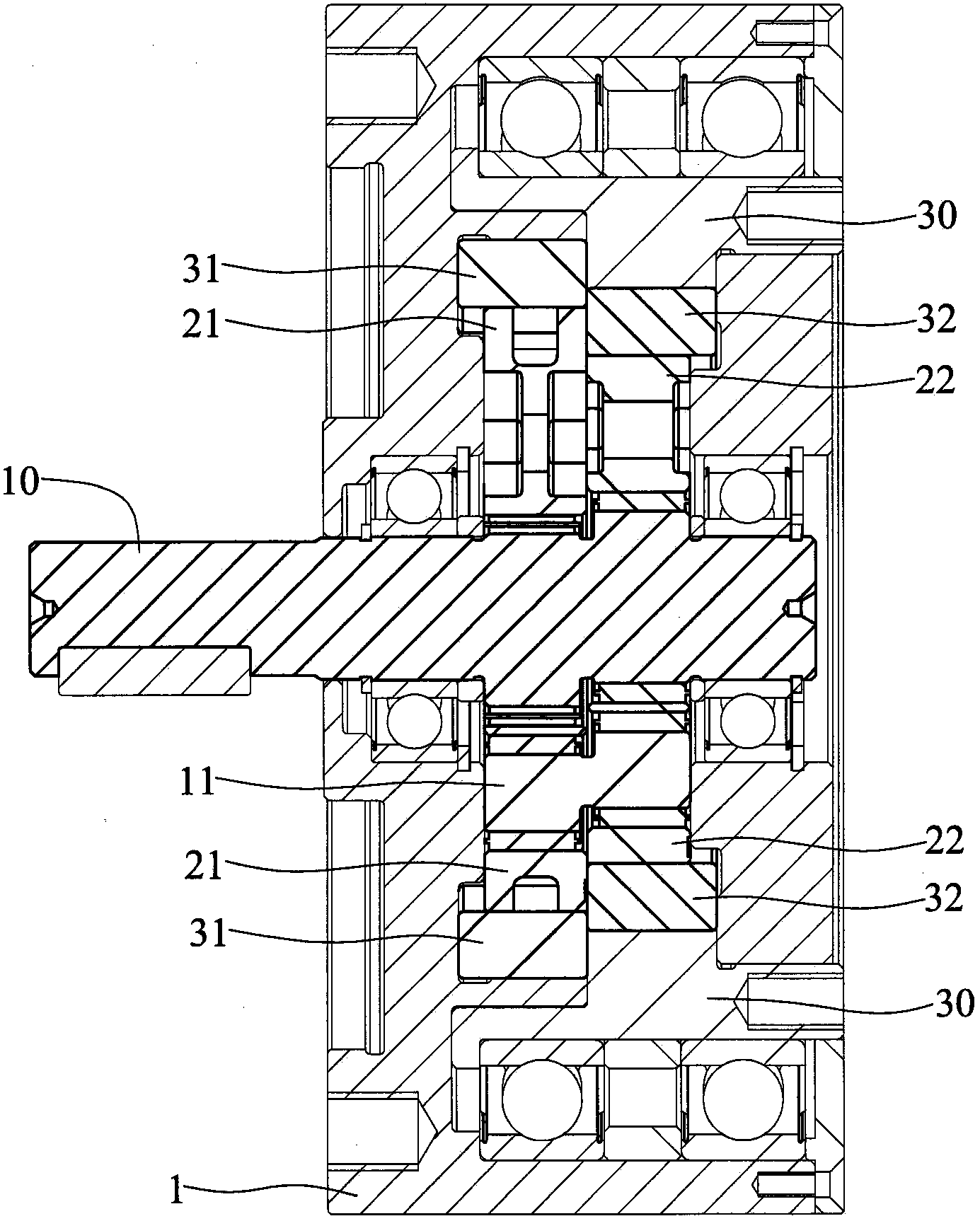
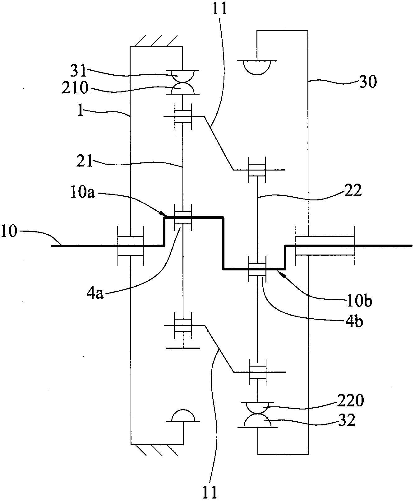
A two-stage differential cycloidal speed reducer with a high reduction ratio is provided, including: a plurality of supporting crank shafts; an input shaft including a first crank shaft portion and a second crank shaft portion; a first cycloidal gear provided on the first crank shaft portion; a second cycloidal gear provided on the second crank shaft portion and connected with the first cycloidal gear through the supporting crank shafts; a plurality of first ring pins provided around the outer circumference of the first cycloidal gear and in sliding contact with a plurality of teeth on the periphery of the first cycloidal gear; a first annular gear with the plurality of first ring pins; a plurality of second ring pins provided around the outer circumference of the second cycloidal gear and being in sliding contact with a plurality of teeth on the periphery of the second cycloidal gear; and a second annular gear with the plurality of second ring pins.

Description

technical field [0001] The invention relates to a speed reducer, in particular to a cycloid speed reducer with two stages of differential speed and high reduction ratio. Background technique [0002] The reducer is a power transmission mechanism that uses gears to reduce the speed of the motor to the desired speed and obtain a larger torque. In the mechanism currently used to transmit power and motion, the application range of the reducer is quite wide, from ships, automobiles and motorcycles, heavy machinery for construction, processing machinery and automatic production equipment used in the machinery industry, to daily life. Common home appliances, clocks and watches, etc., can be seen in the application of reducers from the transmission of large power to the transmission of small loads and precise angles. [0003] The reducers currently used in robots mainly include gear reducers, harmonic reducers (HarmonicDrive), RV reducers, and cycloid reducers. Harmonic Drive main...

Claims


Application Information

Patent Timeline
Patent Type & Authority Applications(China)
IPC IPC(8): F16H1/32F16H57/023
CPCF16H1/32F16H2001/323
Inventor 黄俊弘谢章嘉李志中邱卓群
Owner IND TECH RES INST
Learn More