
Implementation method for communication network 1+1 protective cascading networking

A technology of a communication network and an implementation method, which is applied in the field of 1+1 protection cascade networking in an optical transmission network, can solve problems such as large protection switching delay, complicated system maintenance angle, and low protection switching efficiency, so as to improve stability, The Effect of Simplifying Complexity

Active Publication Date: 2008-03-19
ZTE CORP
View PDF0 Cites 13 Cited by
  • Summary
  • Abstract
  • Description
  • Claims
  • Application Information

AI Technical Summary

Problems solved by technology

[0011] (1) Since the alarm delay time needs to be set for each 1+1 protection section after cascading, in the case of an internal fault in the current protection section, the protection switching also needs to wait for the alarm delay time before it can start, which reduces the protection switching efficiency. Moreover, the more protection sections in 1+1 cascading, the greater the delay of protection switching time in case of internal failure of the downstream protection section
[0012] (2) When the internal fault of the upstream protection section leads to internal protection switching, because the downstream protection section also detects the fault alarm of the upstream signal downlink, although the downstream protection section starts the corresponding alarm delay mechanism relative to its upstream protection section, but due to the network Due to stability and other reasons, it is impossible to fully guarantee that the signal of the upstream protection section completes the protection switching of the local end before the end of the alarm delay time of the downstream protection section, so that the problem of repeated downstream switching cannot be completely avoided.
[0013] (3) Since the alarm delay mechanism needs to be set separately for the order of the upstream and downstream protection segments, and the set time length value is related to the overall performance of the system, it is more complicated from the perspective of system maintenance
[0014] Therefore, in general, the current alarm mechanism has problems such as low protection switching efficiency, large protection switching delay, and complicated system implementation and maintenance.

Method used

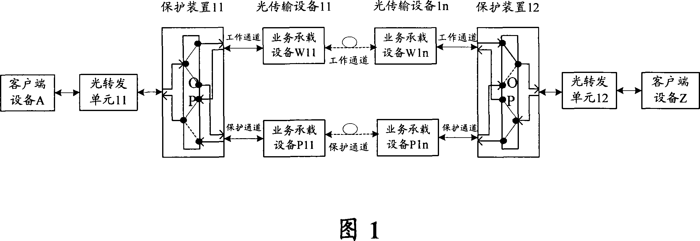
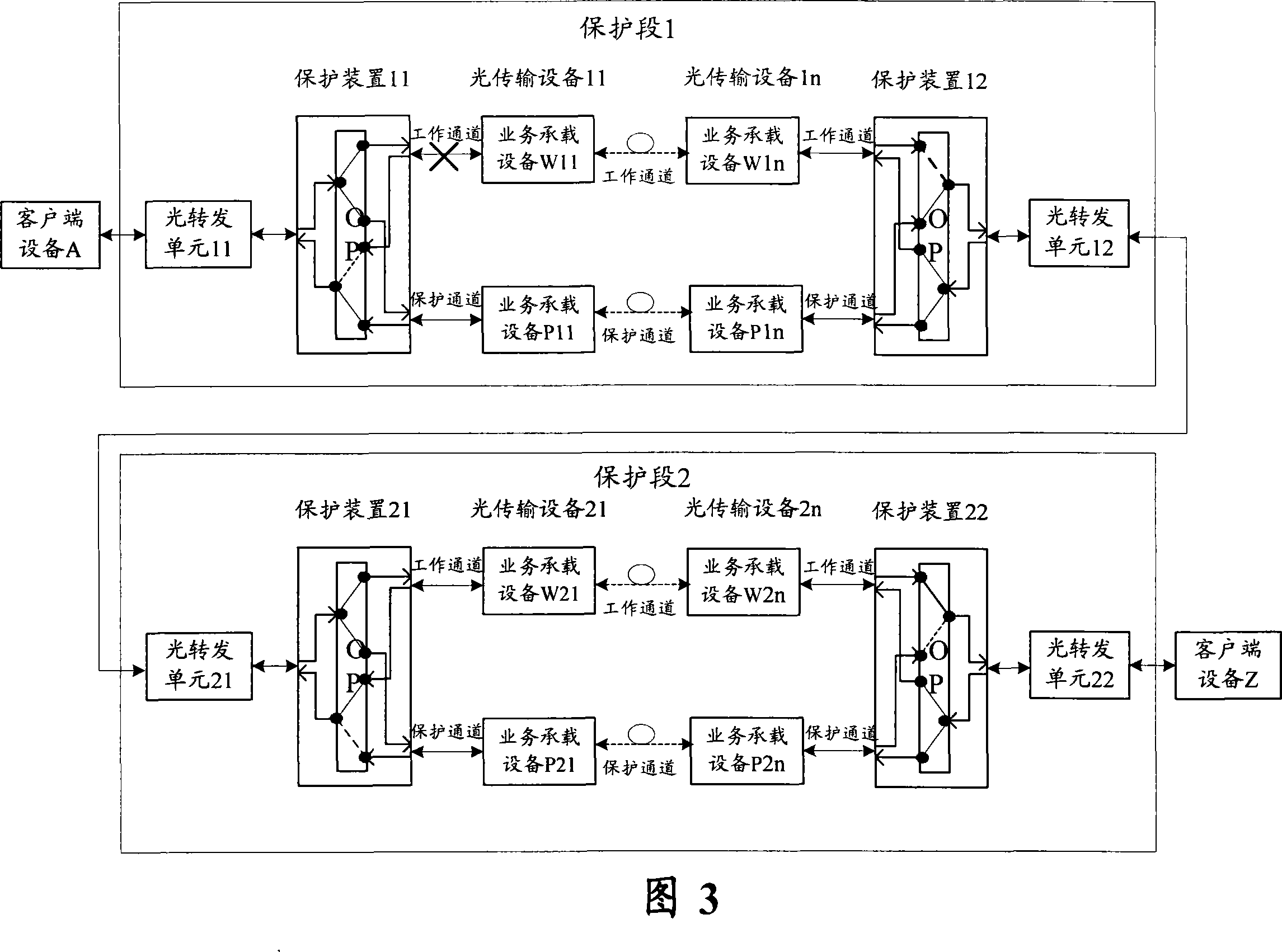

Image

  • Implementation method for communication network 1+1 protective cascading networking
  • Implementation method for communication network 1+1 protective cascading networking
  • Implementation method for communication network 1+1 protective cascading networking

Examples


example

[0047] In this example, the client side of the network bears signals encapsulated and transmitted by an OTN (Optical Transport Network, Optical Transport Network) on the SDH (Synchronous Digital Hierarchy, Synchronous Digital Hierarchy) service line side.

[0048] In the application situation where the OTN service signal specified in ITU-T G.709 is carried in the network, the alarm sets supported by the system are divided into: the external signal alarm set of the protection section Alm1={SD, LOS, LOF}; Alarm set Alm2 to start protection = {ODU-AIS}; alarm set Alm3 to start protection inside the protection section = {LOS, OTU-AIS, SM-BIP8 limit violation, OTU-LOF, ODU-LCK, ODU-OCI}.

[0049] The configurations of the client service transceiver device, the relay service transceiver device, and the terminal service transceiver device adopt the settings already described.

[0050] Afterwards, (1) For the case of ① a line break failure (LOS alarm) in the network, the client servic...


PUM


Abstract

The invention provides an implementation method of '1+1' protection cascaded network of communication network, wherein a task transmitting / receiving device of each protected segment in the communication network is set to treat different types of alarming, including external signal alarming of the protection segment, alarming that doesn't need to start the protection within the protection segment, as well as internal signal alarming in the protection segment. According to the invention, the complexity of system processing is simplified, and, at the same time, the stability of system protection switch is significantly improved.

Description

technical field [0001] The present invention relates to the field of 1+1 protected cascaded networking of communication networks, in particular to a method for realizing 1+1 protected cascaded networking in an optical transmission network using wavelength division multiplexing (Wavelength Division Multiplexing, referred to as WDM) technology , which can effectively solve the coordination problem of upstream and downstream protection sections when multiple 1+1 protection cascade networking applications are applied. Background technique [0002] In traditional optical transport network applications, the network structure is mainly based on chain and ring topologies. In order to ensure the survivability of the network, the 1+1 protection method has been widely adopted due to its easy implementation. [0003] The implementation principle of the 1+1 protection mode can be described as: at the sending end, copy the bearer signal into two copies, and send them along the pre-planned...

Claims


Application Information

Patent Timeline
Patent Type & Authority Applications(China)
IPC IPC(8): H04L12/24H04L1/00H04L12/28
Inventor 王振宇
Owner ZTE CORP
Learn More