
Neon light emulated luminous sign device with reflection edge directly packaged by LED chip

A technology of LED chips and neon lights, which is applied to display devices, lighting devices, and illuminated signs, etc., can solve the problems of long light wave range, scarce light beams, and dim light-emitting brightness of light guide strips, and achieves low price and good effect. , Improve the effect of light efficiency and luminous uniformity

Active Publication Date: 2008-03-19
SHANGHAI SANSI ELECTRONICS ENG +1
View PDF2 Cites 4 Cited by
  • Summary
  • Abstract
  • Description
  • Claims
  • Application Information

AI Technical Summary

Problems solved by technology

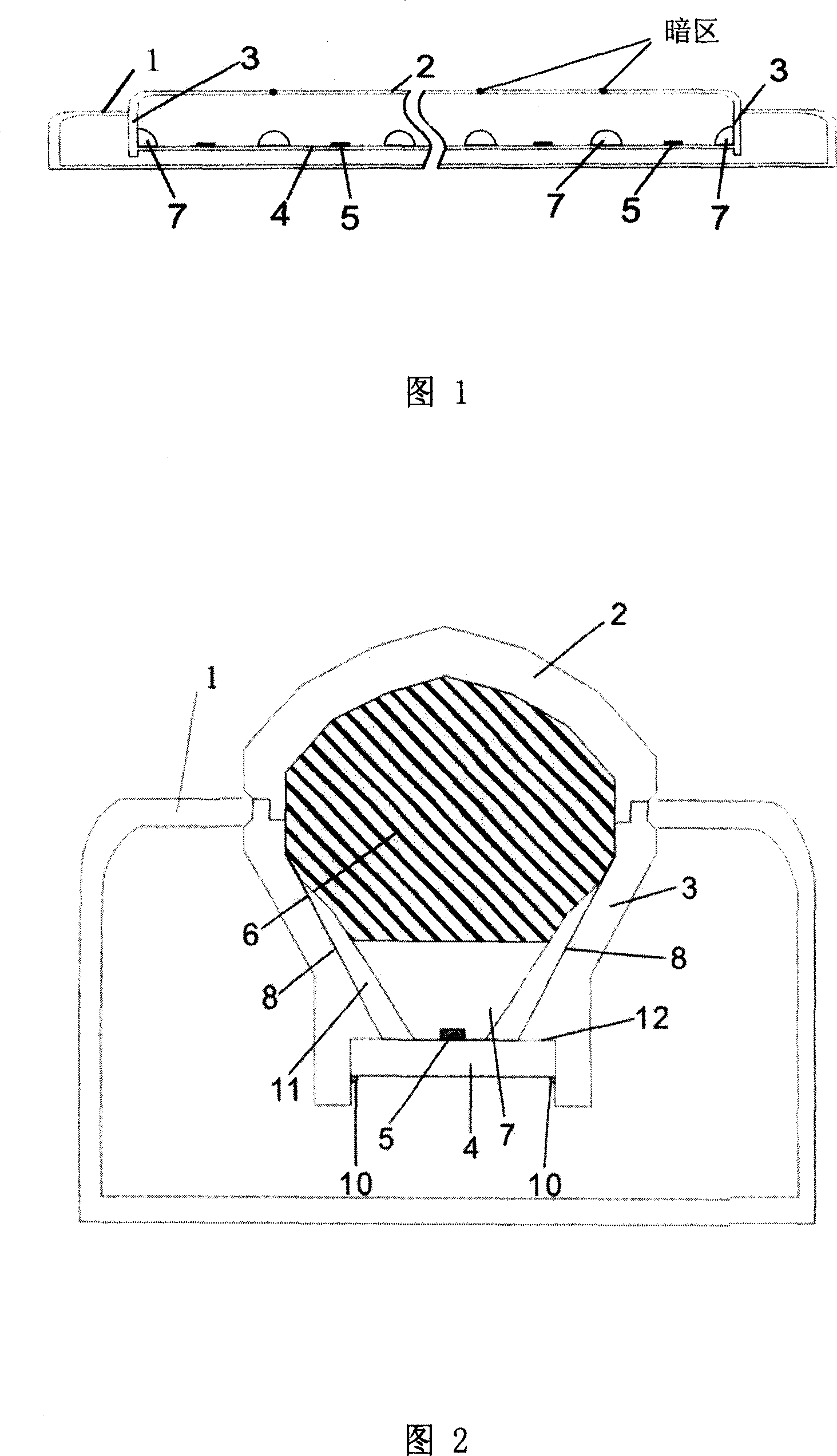
However, judging from the overall display effect of the light guide strip, the luminance of the light guide strip vertically above the midpoint of the distance between two adjacent LED chips is still obviously dark. Compared with the position, the light wave range is the longest. Second, although the light emitted by the LED chip is emitted to the surroundings, compared with other light-emitting areas of the light guide strip, the light beam reflected to this point is relatively rare, thus forming a dark area.

Method used


Image

  • Neon light emulated luminous sign device with reflection edge directly packaged by LED chip
  • Neon light emulated luminous sign device with reflection edge directly packaged by LED chip
  • Neon light emulated luminous sign device with reflection edge directly packaged by LED chip

Examples


Embodiment Construction

[0033]In the following embodiments, the present invention will be further described by using the stroke "-" as a physical device showing a shape.

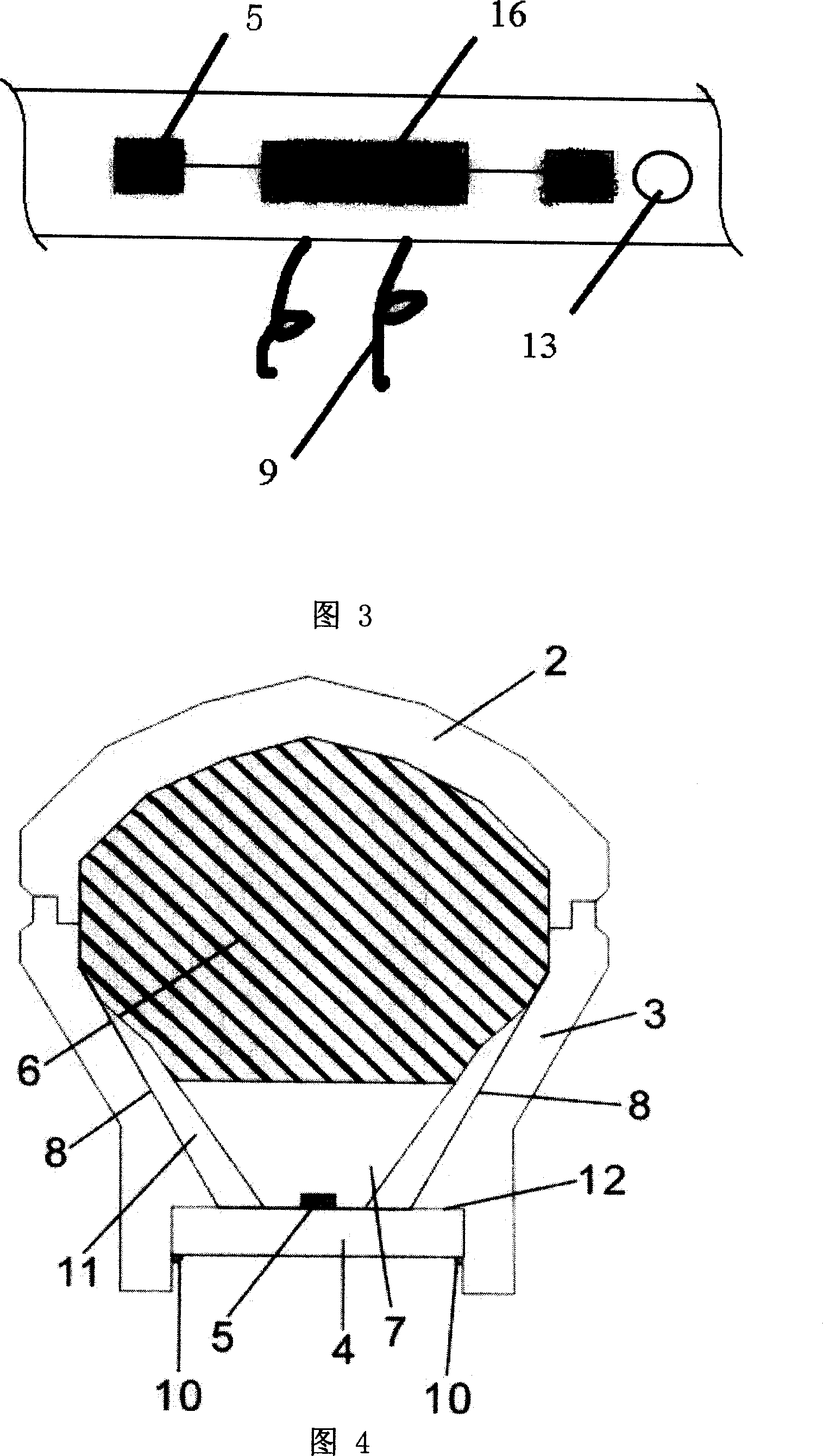
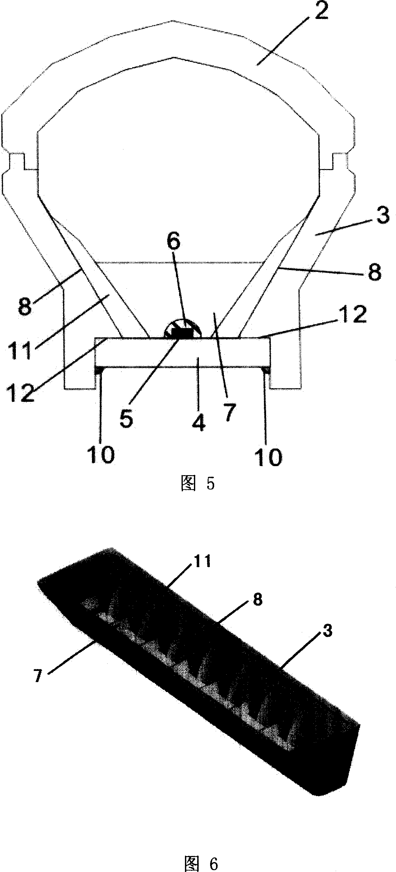
[0034] As shown in Fig. 1 and Fig. 2, a kind of structural shape of the present invention includes the overall frame 1, which can be formed by pressing black ABS plastic, and the shape is not limited. Wherein, the light guide strip 2 identical to the expressed character shape (this embodiment adopts the "one" type display shape) is made of translucent acrylic, and its inner surface is smooth, allowing light to enter freely. The light diffuses from this surface to form a soft luminous surface, and there is a scattering agent inside, so that the light entering the light guide strip can diffuse and accumulate. Both sides below the light guide strip are light grooves 3 made of opaque white PPO (polyphenylene ether) material. The light groove 3 and the light guide strip 2 are pressed into a whole by secondary injection molding. The pur...


PUM


Abstract

The invention discloses a luminescent mark device with a reflecting edge, and is similar to a neon lamp, and the luminescent mark device is directly enclosed with a LED chip. The invention comprises a light guide bar with the shape of the front surface being required character or line shape, lighting grooves made of light tight material and arranged on both sides at the lower part of the light guide bar, and LED lighting chip circuit boards which are also arranged at the lower part of the lighting grooves. The invention is characterized in that the inner side of at least one surface in the three surfaces enclosed by the lighting grooves and the circuit boards is provided with the reflecting edge. Concretely, transverse reflecting edge structures can be added but not be limited at the bottom parts of the lighting grooves, thus the light rays of the LED chip are reflectively reflected to the light guide bar along the circuit board, the light path of the light rays are shortened, the light absorbing of the enclosing material is reduced, and the lighting effect and the lightening uniformity of the device are improved; vertical reflecting edge curved surface structures can also be added but not be limited in the inner surfaces of the lighting grooves, and according to the mathematics ellipse focal point reflection principle, all the lights transmitted to the curved surface by the LED chip are reflected to a specific dark space of the light guide bar, so as to improve the brightness of the dark space.

Description

Technical field: [0001] The invention relates to a luminous advertising sign for display, in particular to a neon-like luminous sign device which is directly packaged by an LED chip and has reflective ribs. Background technique: [0002] Traditional light-emitting advertising devices or other sign devices are mostly made of neon tubes, incandescent lamps or fluorescent tubes, but they have high voltage, poor safety, large volume, inconvenient transportation, short life, generate a lot of heat, consume a lot of energy, and have high operating costs. It is subject to impact and requires professional installation and maintenance. [0003] With the advancement of LED technology, LED has been introduced into the application field of simulated neon lights and has made some progress, but generally a commercially available LED single tube is welded on a circuit board as a light source, and then made into the characters to be displayed or There are two main problems with this approa...

Claims


Application Information

Patent Timeline
Patent Type & Authority Applications(China)
IPC IPC(8): F21S4/00G09F13/00F21V13/02F21V7/00F21V7/22F21V23/00F21W111/00F21Y101/02F21Y115/10
Inventor 周士康成鑫张斌李晟何孝亮
Owner SHANGHAI SANSI ELECTRONICS ENG
Learn More