Split magnet ring on a magnetron sputter chamber

A magnet ring and magnetron technology, which is applied in the process of producing decorative surface effects, decorative arts, etc., can solve problems such as unsatisfactory uniformity

Inactive Publication Date: 2008-03-12
APPLIED MATERIALS INC
View PDF2 Cites 11 Cited by
  • Summary
  • Abstract
  • Description
  • Claims
  • Application Information

AI Technical Summary

Problems solved by technology

On the other hand, when applying Gung's configuration to sputtering a tantalum barrier layer between the via wall and the copper seed layer, the resulting uniformity is not yet fully satisfactory

Method used


Image

  • Split magnet ring on a magnetron sputter chamber
  • Split magnet ring on a magnetron sputter chamber
  • Split magnet ring on a magnetron sputter chamber

Examples


Embodiment Construction

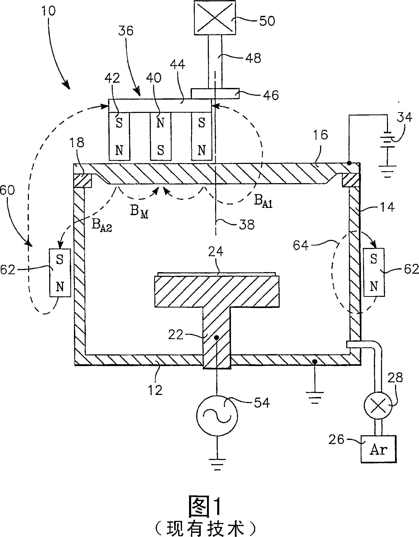
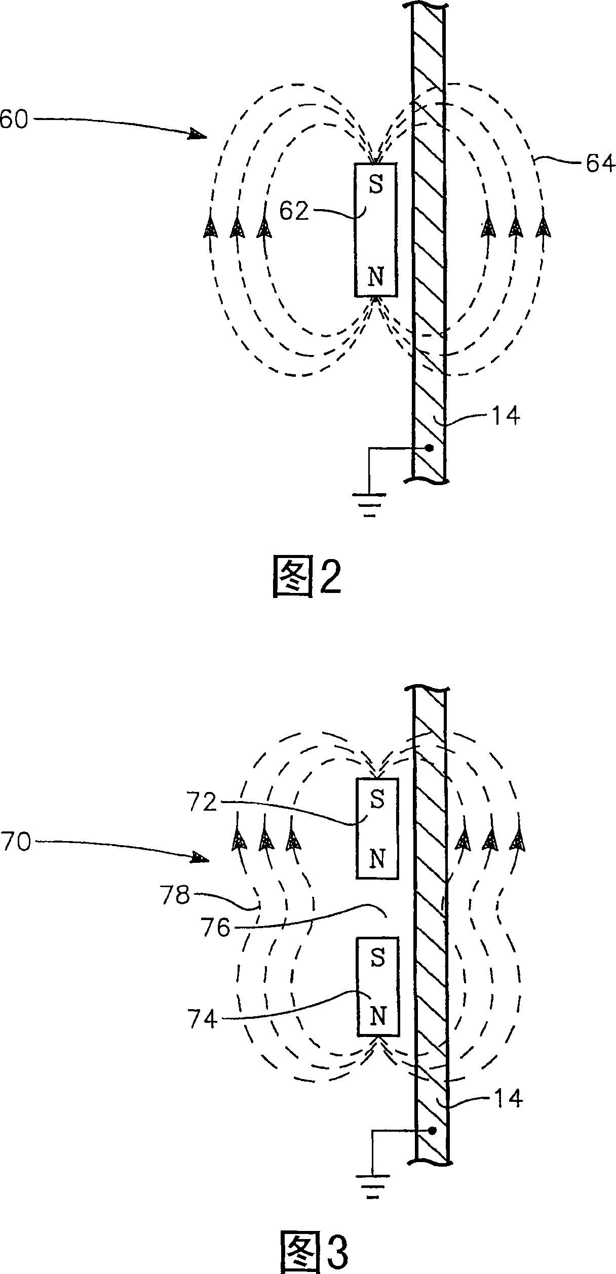
[0025] The inventors believe that the improvement in uniformity achieved by Gung is achieved in part by the magnet ring 62, which produces a generally semi-helical magnetic field 64 that resembles the chamber sidewall on the side of the chamber away from the rotating magnetron 36. 14 or shields the adjacent dipole field, but also exists on the side of the chamber 12 temporarily aligned with the rotating magnetron 36 . As shown in more detail in the schematic front view of FIG. 2 , apart from insignificant secondary effects due to the annular shape of the magnet ring 62 , the magnetic field 64 generated by the magnet ring 62 is a magnetic dipole field. Inside the chamber side wall 14 , the dipole field 64 creates a magnetic shield that hinders the diffusion of the plasma (especially its electrons) to the grounded chamber side wall 14 . Accordingly, the diffusion of plasma comprising sputtered metal ions diffused from the target 16 in the vicinity of the magnetron 46 to the grou...


PUM

PropertyMeasurementUnit
lengthaaaaaaaaaa

Abstract

A split magnet ring (70), particularly useful in a magnetron plasma reactor (10) for sputter depositing tantalum, tungsten, or other barrier metal into a via and also resputter etching the deposited material from the bottom of the via onto the via side walls. The magnet ring includes two annular magnet rings (72, 74) composed of the same axial polarity separated by a non-magnetic spacing (76) of at least the axial length of one magnet and associated pole faces. A small unbalanced magnetron (36) rotates about the back of the target (16) having an outer pole (42) of the same polarity as the ring magnets (72, 74) surrounding a weaker inner pole (40) of the opposite polarity.

Description

[0001] related application [0002] This application claims priority to US Provisional Application 60 / 663,568, filed March 18,2005. technical field [0003] The present invention generally relates to sputtering of materials. In particular, the present invention relates to auxiliary magnets for improving uniformity in magnetron sputtering reactors. Background technique [0004] Sputtering, also known as physical vapor deposition (PVD), is commonly used to deposit layers of metals and related materials in the fabrication of semiconductor integrated circuits. Existing techniques originally developed for copper metallization in silicon integrated circuits have been applied to sputtering refractory metals (such as tantalum) and copper used as interconnect hole structures etched into the dielectric The barrier layer in , copper is used as a seed layer for the final plating of copper to fill the holes. As interconnect hole diameters shrink below 100 nm and hole aspect ratios in...

Claims


Application Information

Patent Timeline
Patent Type & Authority Applications(China)
IPC IPC(8): B44C1/22C03C15/00
Inventor 傅新宇
Owner APPLIED MATERIALS INC
Why Eureka
Try Eureka