Conveyor Belts Using Magnetic Couplings

A technology of couplers and conveyor belts, applied in the field of conveyor belts, can solve the problems of no solution proposed, large-scale conveyor belt beyond the containment range, excessive cost and time, etc., and achieve the goal of reducing the cost and time required for transfer and installation, as well as various problems Effect

Inactive Publication Date: 2016-08-17
佰世尔科技有限公司
View PDF8 Cites 0 Cited by
  • Summary
  • Abstract
  • Description
  • Claims
  • Application Information

AI Technical Summary

Problems solved by technology

[0006] In addition, such an increase in the size of the conveyor belt exceeds the accommodation range of the transfer device such as the robot transfer method that transfers the conveyor belt to the production line.
[0007] In addition, a lot of cost and time will be consumed in the process of moving and reinstalling large conveyor belts
[0008] The technology that is the background of the present invention is disclosed in the Republic of Korea Registered Patent No. 10-0757197 etc., but no solution to the above-mentioned problems has been proposed

Method used


Image

  • Conveyor Belts Using Magnetic Couplings
  • Conveyor Belts Using Magnetic Couplings
  • Conveyor Belts Using Magnetic Couplings

Examples


Embodiment Construction

[0029] Advantages and features and prior methods of the present invention will become apparent with reference to the accompanying drawings and embodiments to be described in detail.

[0030] However, the present invention is not limited by the following embodiments and can be realized in various forms. The purpose of this embodiment is to better illustrate the present invention and provide help for those skilled in the art of the present invention to understand, and the present invention Limited only by the claims. In this specification, the same reference numerals refer to the same elements.

[0031] Next, the bed Song Dynasty using the magnetic coupler of the present invention will be described in detail with reference to the accompanying drawings.

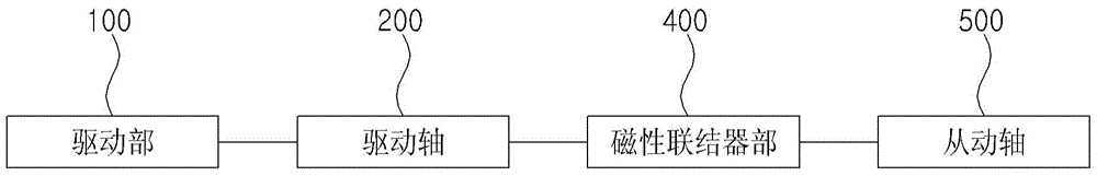
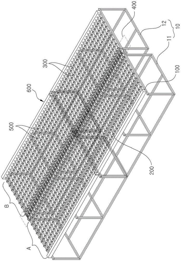
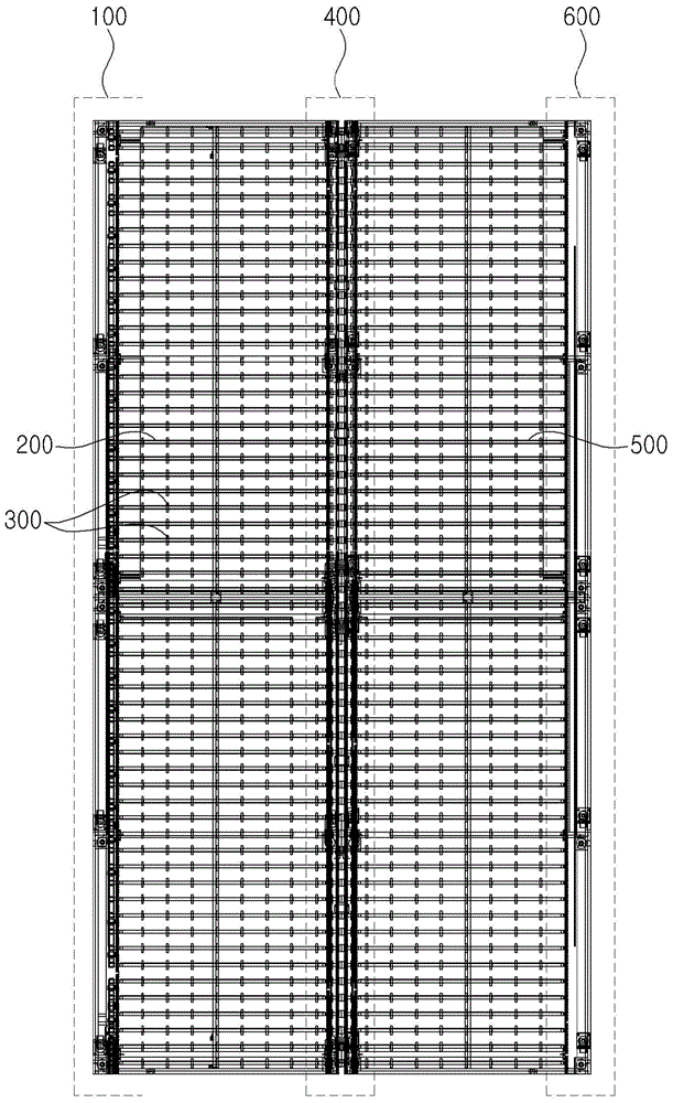
[0032] figure 1 is a schematic structural block diagram of a conveyor belt using a magnetic coupling in a preferred embodiment of the present invention, and Figure 2 to Figure 5 Each is a perspective view, a plan view, a fro...


PUM


Abstract

The present invention relates to a conveyor belt using a magnetic coupling, comprising: a driving part that provides rotational force; a plurality of driving shafts, each of which is combined with a plurality of rotating rollers between one side and the other side, and each end is connected to the above-mentioned driving part rotation; a plurality of driven shafts, each of which is combined with a plurality of rotating rollers between one side and the other side, and one end portion and the other end portion of the drive shaft are each oppositely and rotatably installed; a plurality of magnetic coupling portions, including A drive shaft magnetic coupling coupled to each other end of the drive shaft and formed with a drive shaft magnetic portion alternately formed with a plurality of split magnets, and a drive shaft magnetic coupling coupled to each end of the driven shaft and formed with a drive shaft magnetic portion aligned with the drive shaft magnetic portion. The driven shaft magnetic coupling of the driven shaft magnetic part opposite to each other and forming a magnetic pole pair; when the driving shaft rotates through the driving part, the driven shaft magnetic coupling is in a non-contact state through the magnetic force between the driving shaft magnetic coupling Coordinated rotation, thereby causing the driven shaft to rotate.

Description

technical field [0001] The present invention relates to conveyor belts, and more particularly to the fact that even in the case of large conveyor belts, the conveyor belt can be separated into two parts and installed only by rearranging, thereby significantly reducing the cost and time required for the transfer and installation of large conveyor belts and various parts. This problem with conveyor belts utilizing magnetic couplings. Background technique [0002] This invention relates to conveyor belts. [0003] Existing conveyor belts only provide a structure in which the entirety of one shaft is integrally rotated by a driving part. [0004] As the size of LCD glass, etc., conveyed by the conveyor belt increases, its width also increases. [0005] That is, as the size of LCD glass and the like increases, enlargement of the conveyor belt is an inevitable result. [0006] In addition, such an increase in the size of the conveyor belt exceeds the accommodation range of a tr...

Claims


Application Information

Patent Timeline
Patent Type & Authority Patents(China)
IPC IPC(8): B65G23/22
CPCB65G23/22B65G2812/02148B65G13/00B65G39/02F16D1/00F16D27/01Y02P70/10
Inventor 林殷圣
Owner 佰世尔科技有限公司
Why Eureka
Try Eureka