
Motor

Pending Publication Date: 2021-12-30
LG INNOTEK CO LTD
View PDF0 Cites 0 Cited by
  • Summary
  • Abstract
  • Description
  • Claims
  • Application Information

AI Technical Summary

Benefits of technology

The patent text describes a device that can drive a vehicle at a constant speed and generate an index signal without needing a separate device. This provides a more precise and efficient way to control the vehicle's speed.

Problems solved by technology

The technical problem addressed in this patent text is the need for a driving source to rotate a sensor device and the synchronization of positions of multiple sensor devices using index signals. However, separate devices are required to generate the index signals, which can be cumbersome and costly.

Method used


Image

  • Motor
  • Motor
  • Motor

Examples


Embodiment Construction

[0033]Hereinafter, exemplary embodiments of the present invention will be described with reference to the accompanying drawings.

[0034]However, the technical spirit of the present invention is not limited to some embodiments which will be described and may be realized using various other embodiments, and at least one component of the embodiments may be selectively coupled, substituted, and used to realize the technical spirit within the range of the technical spirit.

[0035]In addition, unless clearly and specifically defined otherwise by context, all terms (including technical and scientific terms) used herein can be interpreted as having customary meanings to those skilled in the art, and meanings of generally used terms, such as those defined in commonly used dictionaries, will be interpreted by considering contextual meanings of the related technology.

[0036]In addition, the terms used in the embodiments of the present invention are considered in a descriptive sense and not for limi...


PUM


Abstract

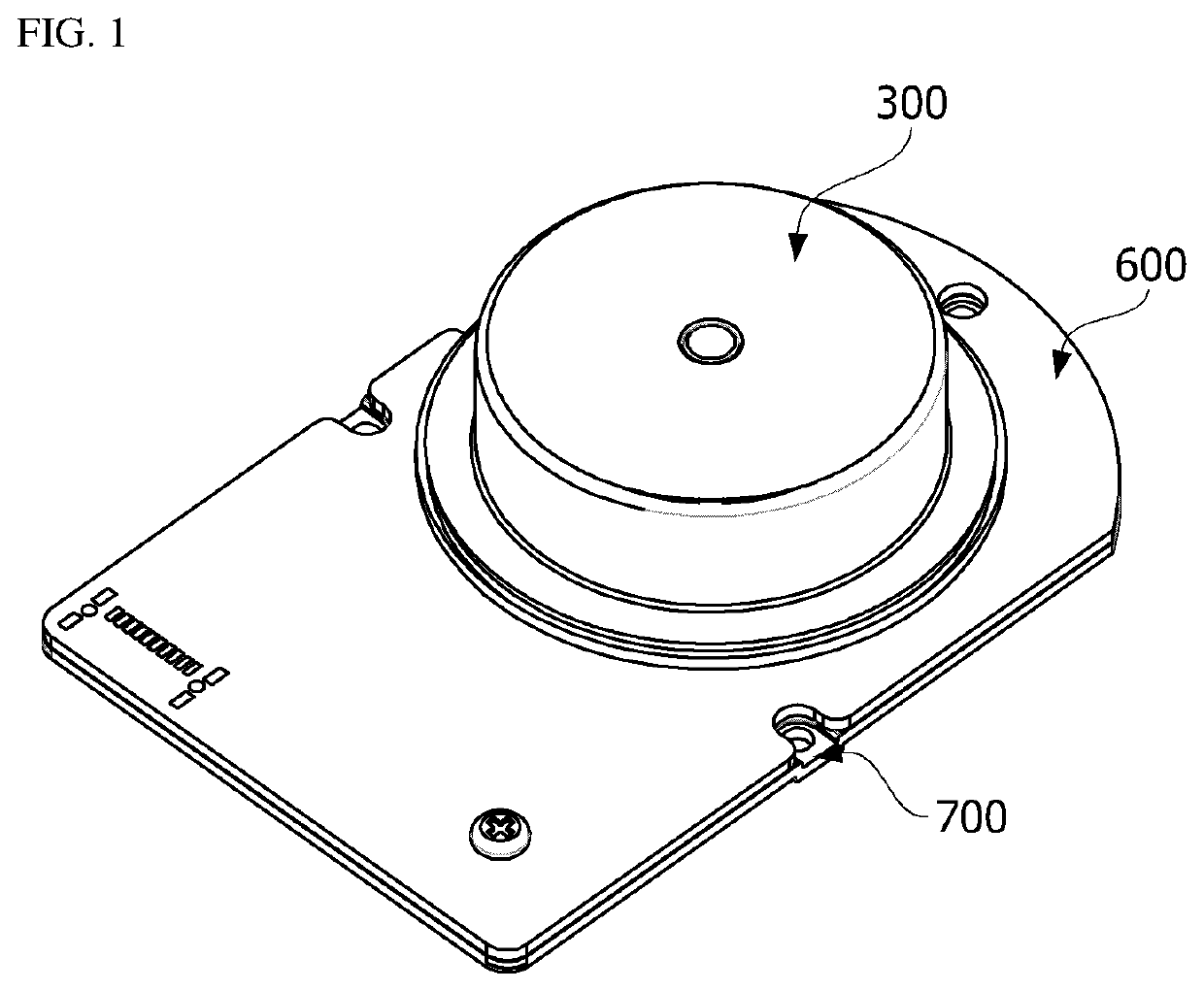
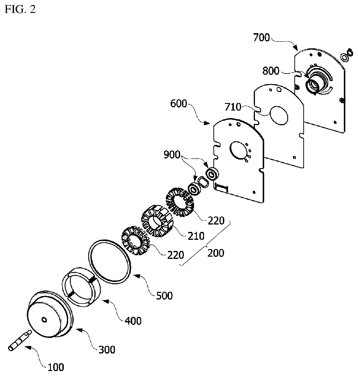
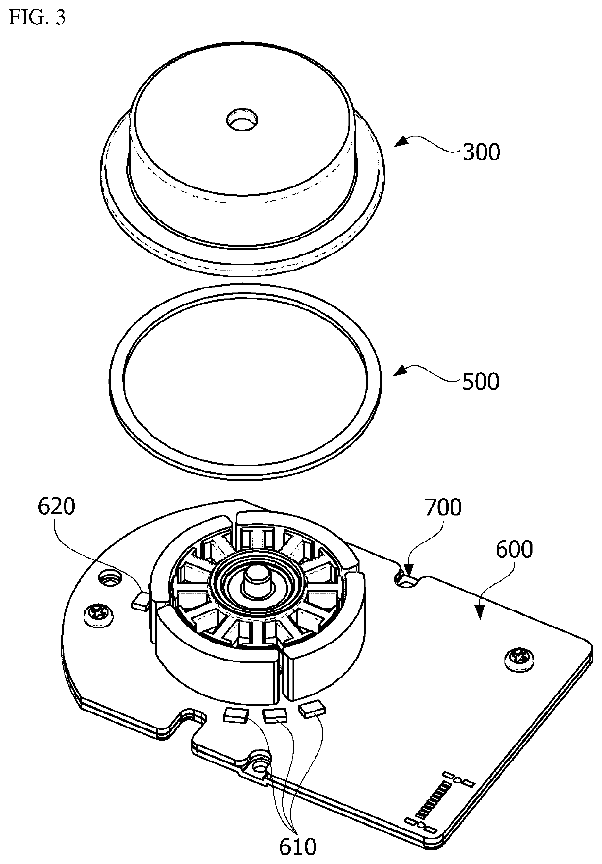
The present invention may provide a motor including a rotary shaft, a yoke coupled to the rotary shaft, a stator disposed between the rotary shaft and the yoke, a first magnet and a second magnet disposed in the yoke, and a circuit board on which a first Hall sensor is disposed to correspond to the first magnet and a second Hall sensor is disposed to correspond to the second magnet, wherein the second magnet includes a plurality of split magnets and one index magnet, a width of the split magnet in a circumferential direction is the same as a width of the index magnet in the circumferential direction, each of the split magnets and the index magnet are formed by combining a first pole and a second pole, a width of the first pole of the split magnet in the circumferential direction is the same as a width of the second pole in the circumferential direction, and a width of the first pole of the index magnet in the circumferential direction is different from a width of the second pole in the circumferential direction.

Description


Claims


Application Information

Patent Timeline
Owner LG INNOTEK CO LTD
Learn More