
Automatic belt cutter

A tape cutting machine and automatic technology, applied in the field of machinery, can solve the problems of complex overall structure, rupture and low degree of automation, and achieve the effect of simple overall structure, high degree of automation and wide application range.

Active Publication Date: 2008-03-05
ZHEJIANG TOPSUN LOGISTIC CONTROL CO LTD
View PDF1 Cites 7 Cited by
  • Summary
  • Abstract
  • Description
  • Claims
  • Application Information

AI Technical Summary

Problems solved by technology

[0004] It can be seen that the overall structure of the device is relatively complex, the degree of automation is not high, and it is not very convenient to operate and use.
On the other hand, the design of the cutting structure of the device is not reasonable enough, and it is easy to cause cracks during the cutting process.
The scope of its application can only be limited to the cutting of paper, the cutting method is single, and the scope of application is limited

Method used


Image

  • Automatic belt cutter
  • Automatic belt cutter

Examples


Embodiment Construction

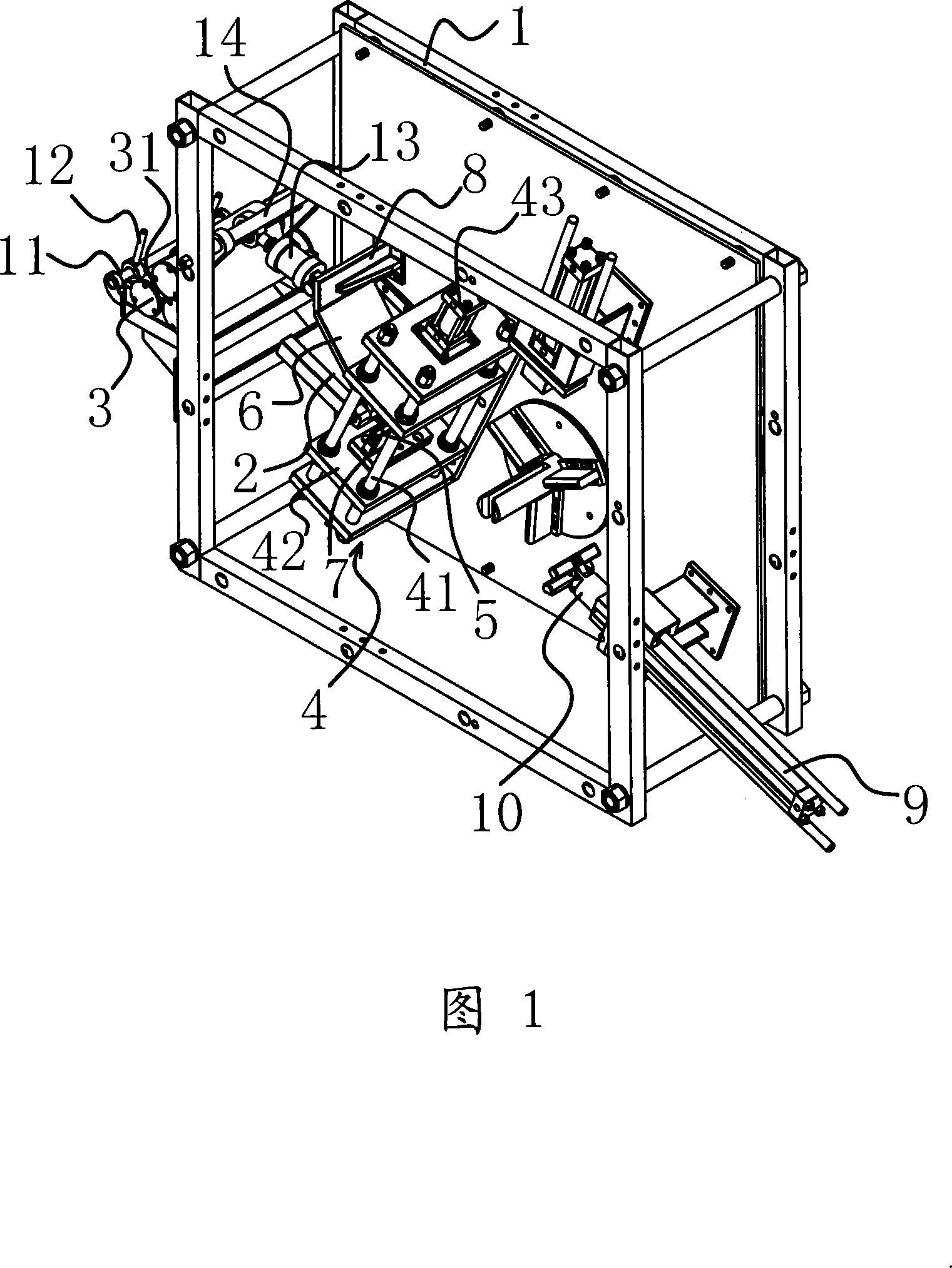
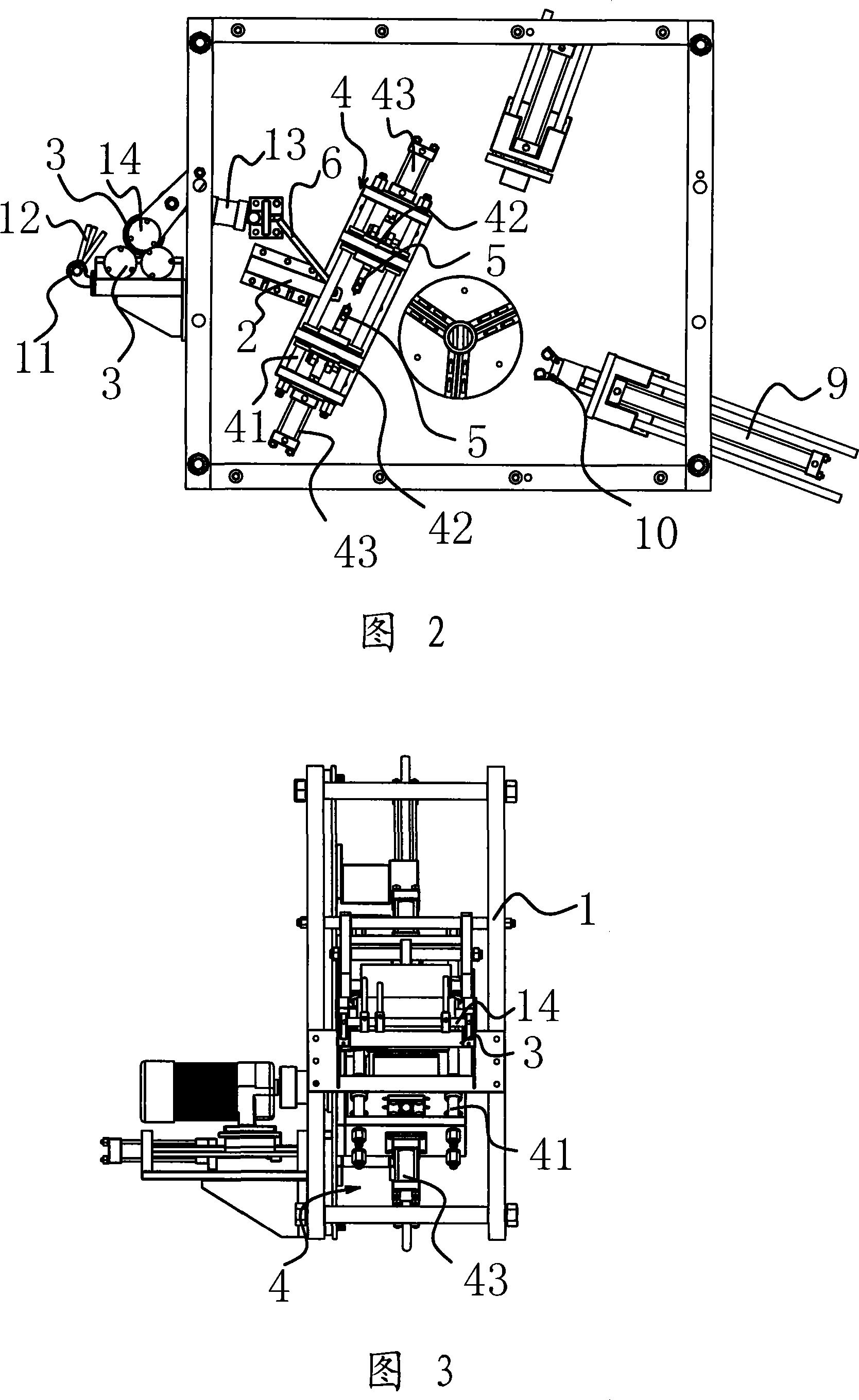
[0022] As shown in Figure 1 and Figure 2, the automatic tape cutting machine is composed of frame 1, worktable 2, roller 3, knife holder 4, cutter 5, cutting mechanism, grasping mechanism and other parts.

[0023] The workbench 2 is set on the frame 1. On one side of the workbench 2, there are three rollers 3 mounted on the frame 1 and arranged parallel to each other, and the three rollers 3 are arranged in a pin shape, and the belt can be removed from the roller 3. The gap 31 between them passes through. A grabbing mechanism for grabbing the end of the belt is provided on the other side of the workbench 2, and a cutting mechanism for cutting the belt is provided between the roller 3 and the grabbing mechanism.

[0024] During operation, the belt passes through the gap 31 between the rollers 3, and the gripping mechanism can grasp the belt and stretch it. When it is necessary to cut off, the cut-off mechanism works. The present invention can also work with the winding mechanism to...


PUM


Abstract

The present invention provides one kind of automatic belt cutting machine, and belongs to the field of mechanical technology. The automatic belt cutting machine includes one frame, one worktable on the frame, at least two parallel drums set on one side of the worktable to form one gap in between for the belt to pass through, one belt end grasping mechanism set on the other side of the worktable, and one belt cutting mechanism between the drums and the belt end grasping mechanism. The automatic belt cutting machine has the features of high efficiency and wide application range.

Description

Technical field [0001] The invention and the field of mechanical technology, in particular, relates to an automatic tape cutting machine. Background technique [0002] Automatic tape cutting machines are widely used in various industries. In order to improve its working performance, people have proposed various improvement schemes on the basis of the existing technology, and some have also applied for patents. [0003] For example, the Chinese patent document discloses an automatic laminating roll paper slitting machine [Patent No.: CN03260823.3], the whole machine includes organism, guide roller, paper conveying guide roller, acceleration guide roller and encoder. The paper conveying guide roller and the accelerating guide roller are mounted on the machine body through bearings, and the center distance of the two guide rollers is determined. The movement of the paper conveying guide roller is driven by the pulley of the speed regulating motor. The main feature is that the accele...

Claims


Application Information

Patent Timeline
IPC IPC(8): B65H35/06B26D1/06B26D7/20B26D5/12B26D7/10
Inventor 阮卜琴
Owner ZHEJIANG TOPSUN LOGISTIC CONTROL CO LTD
Learn More