Eureka AIR delivers breakthrough ideas for toughest innovation challenges, trusted by R&D personnel around the world.

Cylinder device and method for manufacturing the same

A manufacturing method and cylinder block technology, applied in the direction of manufacturing tools, liquid shock absorbers, resistance welding equipment, etc., can solve problems such as increased manufacturing costs, and achieve the effects of reduced manufacturing costs, safe manufacturing, and pollution suppression

Active Publication Date: 2008-02-27
HITACHI LTD
View PDF2 Cites 3 Cited by
  • Summary
  • Abstract
  • Description
  • Claims
  • Application Information

AI Technical Summary

Problems solved by technology

However, in this case, in order to integrally form a large-diameter cover portion with a diameter difference greatly different from that of the mounting member, the manufacturing of the mounting member has to rely on casting, and an increase in manufacturing cost cannot be avoided.

Method used


Image

  • Cylinder device and method for manufacturing the same
  • Cylinder device and method for manufacturing the same
  • Cylinder device and method for manufacturing the same

Examples


Embodiment Construction

[0037] Hereinafter, the best mode for carrying out the present invention will be described with reference to the drawings.

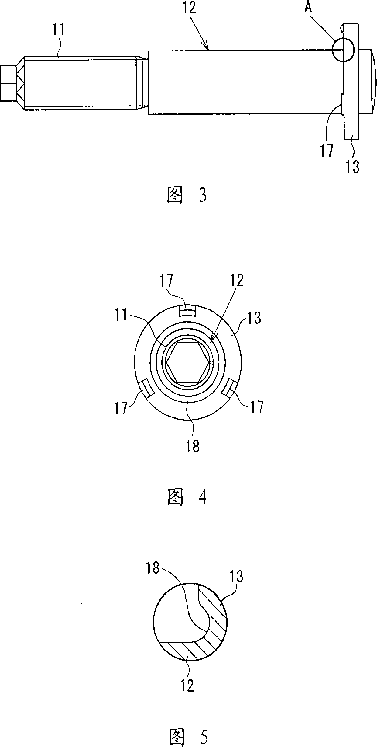
[0038] Fig. 1 shows a hydraulic shock absorber as an embodiment of the present invention. This hydraulic shock absorber is equipped on the suspension of an automobile, and its basic configuration is the same as that shown in FIG. 6 above, so the same symbols are used for the same parts here. In this embodiment, the connecting rod 2 telescopically extending from the cylinder 1 is constructed by butt-joining the connecting rod main body 10 extending from the cylinder 1 and the mounting member 12 having a bolt-shaped portion 11 at the front end as in the conventional art. Then, as shown in FIG. 2 , a flange portion 13 is integrally formed on the end side of the mounting member 12 that abuts with the connecting rod body 10 , and a cover 14 for mounting the above-mentioned protective rod is superimposed on the flange portion 13 .

[0039] In this embodiment,...


PUM


Abstract

The present invention relates to a cylinder device and the making method, which will not lead to substantial increase of the manufacturing cost or the reduction of the jointing strength and can increase the tolerance of the cover body to the vibration. In the hydraulic bumper of the connecting rod (2) which is formed by butt-jointing the connecting rod main body (10) extending from the cylinder body (1) and the installing component (12) with a front end becoming the bolt shape part (11), and the connecting rod extends telescopically from the cylinder (1), a flaunching part (13) forms integratedly at the end side of the installing component (12) butt-jointing to the connecting rod main body (10), a flat part (16) which is used to install the cover body (14) of the protecting cover (4) is superposed on the flaunching part (13), the flaunching part and the flat part is jointed by projection welding. The torque moment which functions on the casing (14) in the swing rotating direction is borne by the wide flat surface of the cover body (14), therefore, the stress produced on the casing (14) is dispersed with a wide range, and the result is that fatigue cracking is hard to generate on the cover body even if at the condition that the RV vehicle, etc. function a furious vibration on the cover body (14).

Description

technical field [0001] The present invention relates to a cylinder device such as a hydraulic shock absorber, a fluid pressure cylinder, and a gas spring, and particularly relates to a cylinder device suitable for a suspension of an automobile and a method for manufacturing the same. Background technique [0002] For example, a hydraulic shock absorber equipped on the suspension of an automobile is shown in Fig. 6, which includes a cylinder body 1, a connecting rod 2 extending telescopically from the cylinder body 1, and a connecting rod 2 embedded in a cylinder extending from the cylinder body 1. part of the cover body 3. In this type of hydraulic shock absorber, the bottom of the cylinder 1 is attached to the suspension arm (not shown), and the front end of the link 2 is attached to the vehicle body via the bolt-shaped portion 2a. Next, a protective cover 4 for protecting the connecting rod 2 is installed on the outer peripheral portion of the cover body 3 . [0003] How...

Claims


Application Information

Patent Timeline
IPC IPC(8): F16F9/10F16F9/32F16F9/38B23K11/00
Inventor 大仓公广
Owner HITACHI LTD
Why Eureka
Eureka Blog
Learn More