
Liquid crystal display

A liquid crystal display and component technology, which is applied in the field of liquid crystal displays, can solve problems such as discontinuous misdirection defects, insufficient liquid crystal molecules 208, and inability to view images, so as to achieve the effect of avoiding light leakage and strong dumping force

Inactive Publication Date: 2008-02-20
WINTEK CORP +1
View PDF0 Cites 18 Cited by
  • Summary
  • Abstract
  • Description
  • Claims
  • Application Information

AI Technical Summary

Problems solved by technology

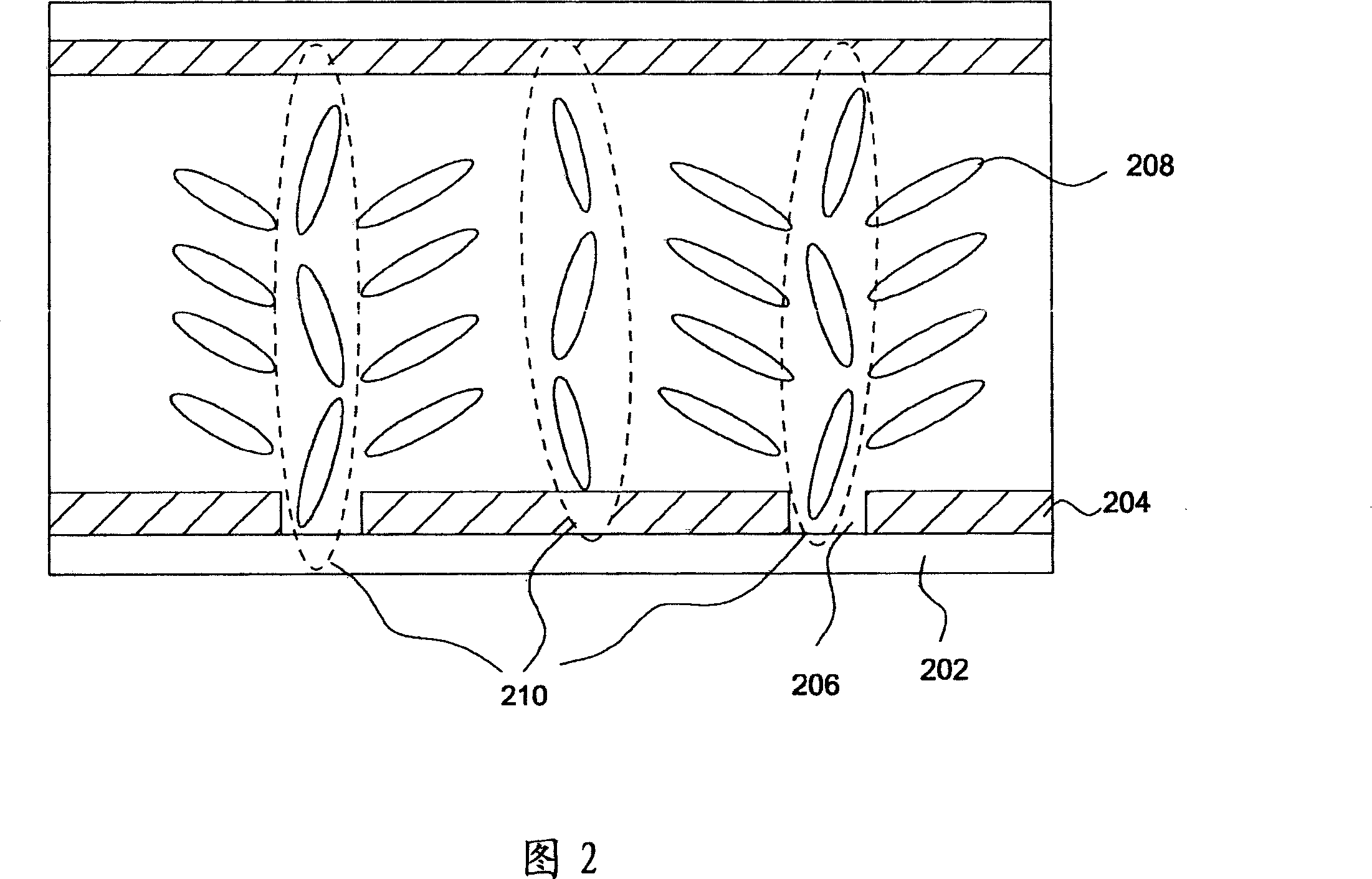
However, the way to form the slit 206 at the electrode 204 must carefully consider the width of the slit 206 itself and the distance between the two slits 206, etc. Otherwise, the force generated by the slit 206 to make the liquid crystal molecules 208 fall is easily insufficient.
Furthermore, the design of the slit 206 causes the energy of the liquid crystal molecules 208 to rotate in either direction to be equal, so that the alignment distribution of the liquid crystal molecules 208 in space produces discontinuous disclination.
The misalignment defect region 210 is easily formed above the slit 206 and between the two slits 206, thereby reducing the overall light transmittance
[0006] On the other hand, when the liquid crystal display can only be used in the see-through mode, the backlight can only be used to display the picture. If it is under sunlight or strong ambient light, the user cannot easily Recognize the display image; on the contrary, when the LCD display can only be used in reflective mode, it can only be used under strong ambient light sources, and it is impossible to view clear images after leaving this strong light source environment

Method used


Image

  • Liquid crystal display
  • Liquid crystal display
  • Liquid crystal display

Examples


Embodiment Construction

[0043] 3A and FIG. 3B are schematic diagrams showing a transflective liquid crystal display 10 according to an embodiment of the present invention, wherein FIG. 3A is a schematic top view viewed from the normal direction of the array substrate, and FIG. 3B is along A-A of FIG. 3A 'The section view obtained by line cutting and unfolding.

[0044] FIG. 3A is a schematic top view showing a plurality of picture elements 12 constituting the transflective multi-domain liquid crystal display 10 . In this specification, the term "pattern element" refers to the smallest addressable display unit in the display area of ​​a liquid crystal display device. For example, in a color liquid crystal display device, each red (R), green (G), or blue (B) sub-pixel (sub-pixel) corresponding to a pixel is a pattern element.

[0045] As shown in FIG. 3A, a plurality of parallel scan lines (scanline) 14 and mutually parallel data lines (data line) 16 are formed on an array substrate, and two adjacent ...


PUM


Abstract

The utility model provides a liquid crystal display, comprising a plurality of first and second pattern elements and a plurality of first and second auxiliary electrodes. The first and second pattern elements are with contrary polarity on a same image plane controlled with time sequence by a reversal drive, and both the first and second pattern elements have a reflecting zone and a transmission zone. A plurality of first auxiliary electrode connected with the first pattern element and a plurality of second auxiliary electrode connected with the second pattern element, wherein, the first pattern element and the second pattern element are separately and partially at least enclosed by the second auxiliary electrode and the first auxiliary electrode to form the edge electric field. The utility model has the advantages that the liquid crystal display can provide stronger overturn force of liquid crystal molecules with the help of edge electric field effectiveness generated by the different polarities of the auxiliary electrode and pixel electrode to increase the effective area of the display zone and promote effectively the integral light penetration rate of the liquid crystal display.

Description

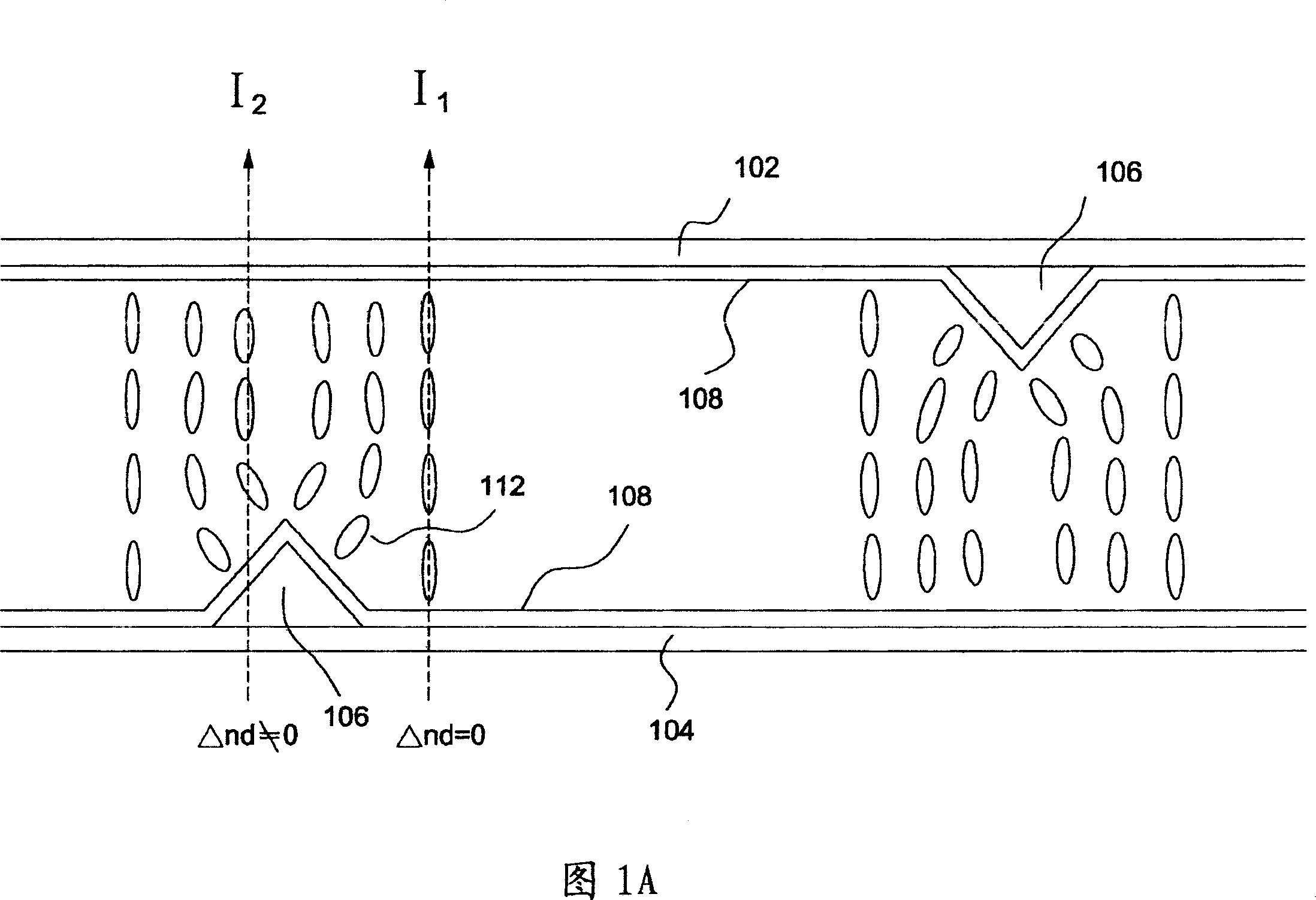
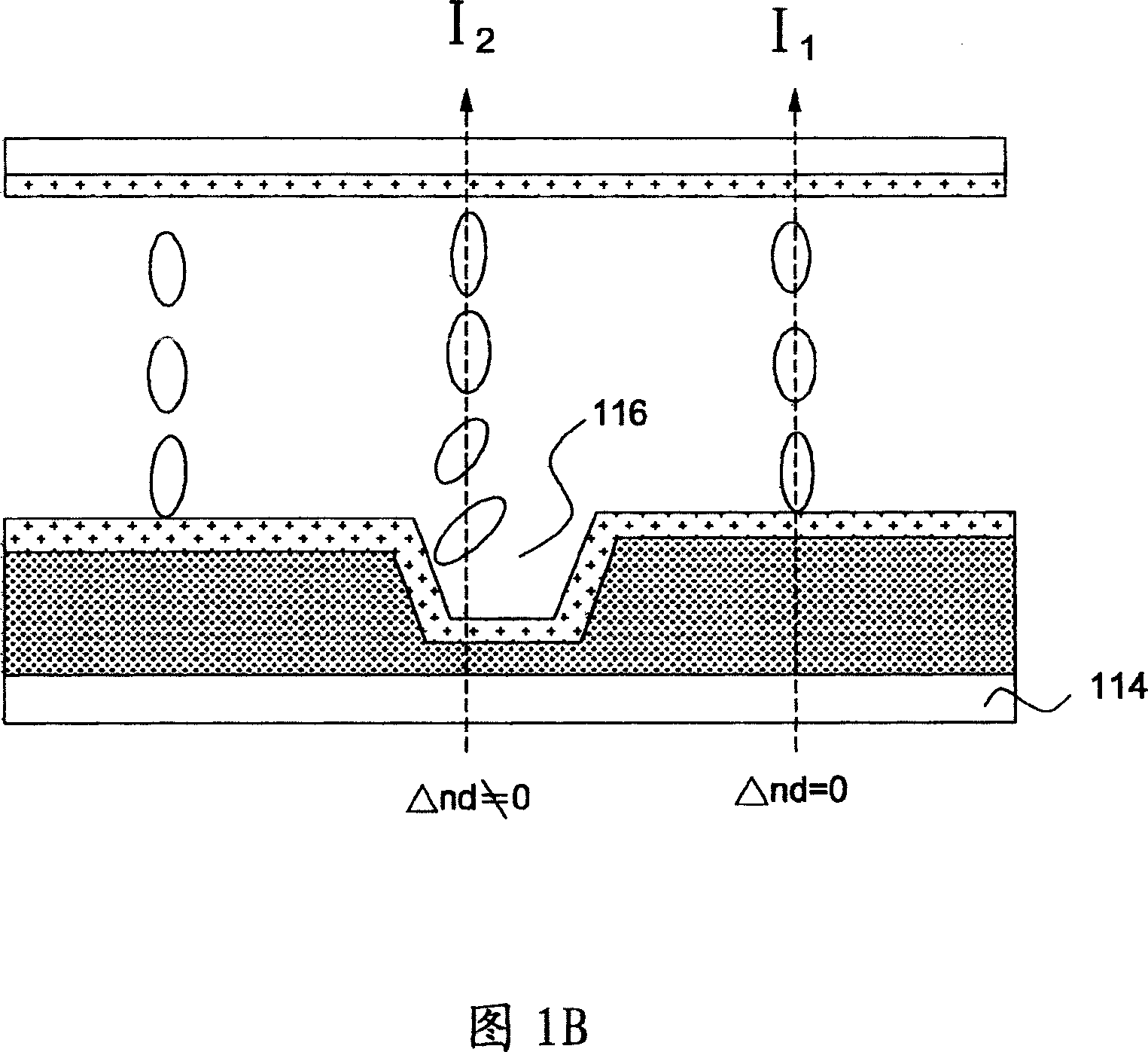
technical field [0001] The present invention relates to a liquid crystal display, especially a liquid crystal display with multi-domain alignment Background technique [0002] It is known that a negative type liquid crystal material with a negative dielectric anisotropy is used to form a liquid crystal alignment method of vertical alignment or homeotropic alignment. When no voltage is applied, the liquid crystal molecules are aligned vertically. Arranged in the form of substrates, it can provide good contrast (contrast) performance. However, generally, in order to form a multi-domain splitting effect in a vertically aligned LCD, the matched structure may have some light leakage or insufficient multi-domain splitting configuration capability. [0003] FIG. 1A is a schematic cross-sectional view showing the design of a conventional multi-domain vertically aligned LCD (multi-domain vertically aligned LCD; MVA LCD). As shown in FIG. 1A, bumps 106 are formed on the upper and lo...

Claims


Application Information

Patent Timeline
Patent Type & Authority Applications(China)
IPC IPC(8): G02F1/133G09G3/36
Inventor 王文俊刘锦璋王义方游明璋
Owner WINTEK CORP
Learn More