
Cone-beam CT system plate detector image anti-interference calibration method

A flat-panel detector, correction method technology, applied in image enhancement, image data processing, image data processing and other directions, can solve the problem of not completely effective removal of artifacts, etc., to achieve the effect of removing linear and ring artifacts

Inactive Publication Date: 2008-02-20
NORTHWESTERN POLYTECHNICAL UNIV
View PDF0 Cites 32 Cited by
  • Summary
  • Abstract
  • Description
  • Claims
  • Application Information

AI Technical Summary

Problems solved by technology

[0011] In order to overcome the inadequacy of the prior art that cannot fully effectively remove artifacts, the present invention provides an anti-interference correction method for flat-panel detector images in a cone-beam CT system, which can obtain high-quality projection images and reconstructed slice images

Method used


Image

  • Cone-beam CT system plate detector image anti-interference calibration method
  • Cone-beam CT system plate detector image anti-interference calibration method

Examples


Embodiment Construction

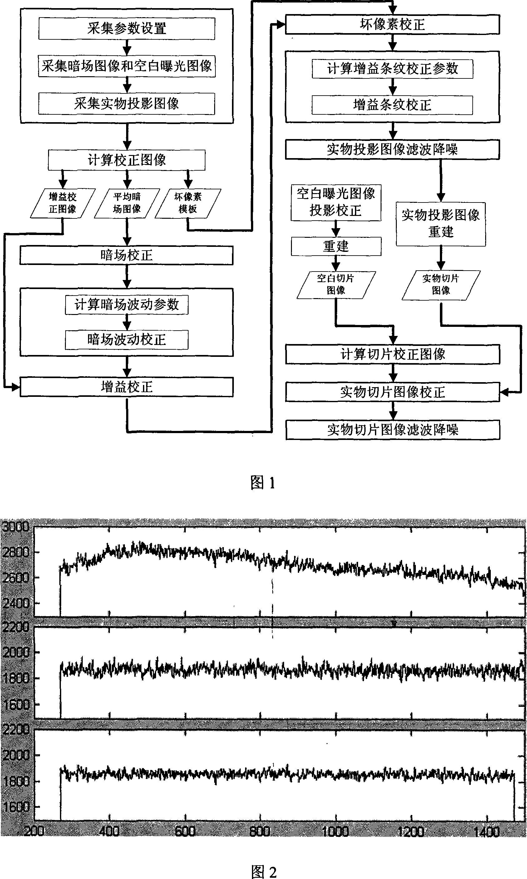
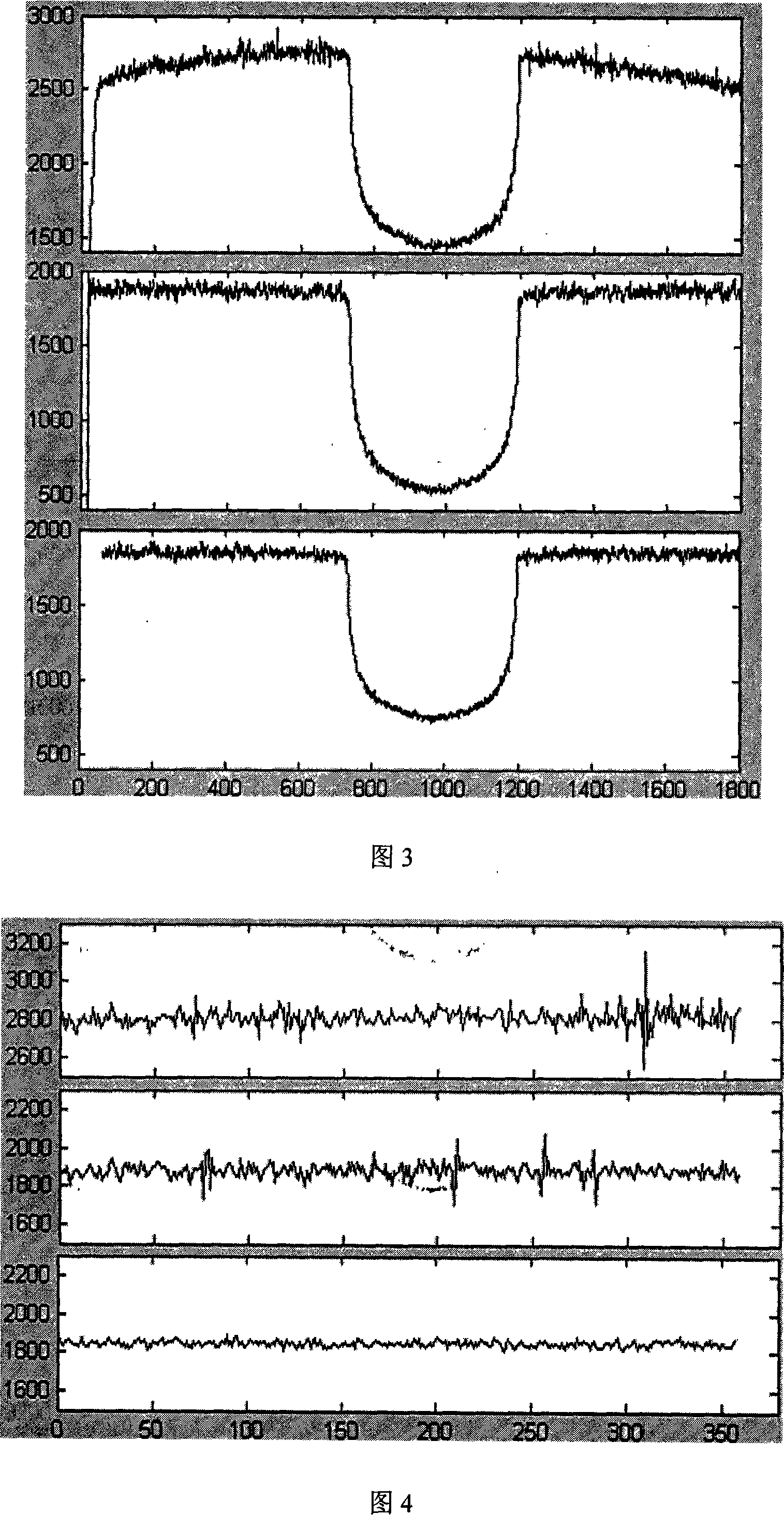
[0043] As shown in Figure 1, this example selects a cylindrical aluminum part to verify the correction effect, and the operation process is as follows:

[0044] 1. Parameter adjustment and data collection can be subdivided into the following three main steps:

[0045] (1) Adjust the acquisition parameters (such as ray source voltage, current, flat panel detector exposure time, etc.) according to the measured object, so that the output of the flat panel detector can be kept in a region with better linearity. Install a rectangular shielding plate (the direction of the long side of the rectangle is the column direction) so that it shields the pixel output of 100 columns.

[0046] (2) Under the acquisition parameters, a certain number of dark field images and blank exposure images are collected. The number of dark field images depends on the stability of the dark field. The worse the stability, the greater the number of images collected. In this example, 360 dark field images are...


PUM


Abstract

The utility model discloses an anti-interference correction method of flat panel detector image in cone-beam CT system, which is characterized in that collection parameter is set, the plat panel detector is shielded partially, dark image, blank exposure image and object projection image are collected; average dark field image, gain correction image and bad pixel template image are calculated; dark field correction, dark field fluctuation correction, gain correction, bad pixel correction and gain strip correction are made on the object projection image; the filtering de-noising treatment is made on the object projection image, the object segmentation image is re-constructed by the object projection image. The blank exposure image is reconstructed to be a blank segmentation image, the segmentation correction image is calculated; the segmentation correction is made on the object segmentation image; the filtering de-noising treatment is made on the object segmentation image. The utility model has the advantages that the correction result is obviously better than that of the prior correction calculation method, enabling. to effectively dispose the linear and annular artifacts that can not be eliminated by the prior correction method, moreover image signal-to-noise ratio is higher or equal to the prior level.

Description

technical field [0001] The invention belongs to the field of computer image processing, and relates to a set of correction solution corresponding to the output image of a flat panel detector used in a CT system. Background technique [0002] High-resolution cone-beam CT is the most promising high-tech technology to solve non-destructive testing problems in the world today, involving many disciplines such as radiology, graphics and imaging, mathematics, physics, mechanics and computers. Compared with traditional CT, cone-beam CT can obtain hundreds or even thousands of cross-sectional projections at a time, with high scanning speed, small slice thickness, isotropic spatial resolution, and high precision. One of the main differences between cone-beam CT and traditional CT is to use a flat panel detector as the acquisition part of the projected image. [0003] Flat panel detector is a new generation of digital X-ray area array imaging equipment based on large-scale amorphous s...

Claims


Application Information

Patent Timeline
Patent Type & Authority Applications(China)
IPC IPC(8): G01N23/04G06T5/00G06T1/00
Inventor 张定华黄魁东卜昆王苦愚
Owner NORTHWESTERN POLYTECHNICAL UNIV
Learn More