Connecting fitting
A technology for connectors and connecting components, which is applied in the field of connectors, spring hooks or connectors made of synthetic resin, can solve the problems of not being able to use spring hooks, etc., and achieve the effect of improving the locking strength and good quality
- Summary
- Abstract
- Description
- Claims
- Application Information
AI Technical Summary
Problems solved by technology
Method used
Image
Examples
Embodiment 1
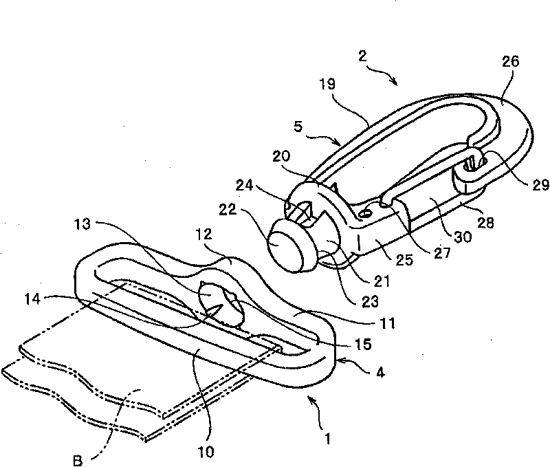
[0043] Figure 1-8 The connector of the shown embodiment 1 is as described above, the first member 1 of the connector is formed by the belt connecting member 4, the second member 2 is formed by the spring hook 5, and the two members 4, 5 use thermoplastic resin injection molding to prevent Take off the whole outside the sheet 28. Although the fall-off preventing piece 28 is formed of a wire, the same resin as the spring hook 5 may be used to integrally form one fall-off preventing piece 28 on the back surface of the base 20 . The hook portion 26 of the spring hook 5 projects a hook portion 26 of a T-shaped section on the back side of the circular abutment 20, forms a reinforcement portion of the same width on the outside of the hook portion 26, and forms a reinforcement portion of the same thickness on the inside. hook. In addition, on the back side of the base 20, a short-sized support part 25 is provided in the form of being provided with the hook part 26 together, and two...
Embodiment 2
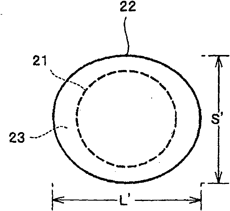
[0049] Figure 9 The connector of the illustrated embodiment 2 is such that the form of the locking portion 23 of the enlarged portion 22 of the above-mentioned embodiment 1 is changed from image 3 In the state where the shown form is staggered by 90 degrees, the direction of the main body 19 of the spring hook 5, that is, the locking portion 23 of the enlarged portion 22 in the same direction as the hooking direction of the hook portion 26 can be set as the minor axis S′, and The locking portion 23 of the enlarged portion 22 in the direction perpendicular to the direction of the hook portion 26 is the major axis L′. Other constitutions are the same as the previous example. The use form of the snap hook 5 in this case is suitable for an implementation form with a phase difference of 90 degrees from that of the first embodiment described above.
Embodiment 3
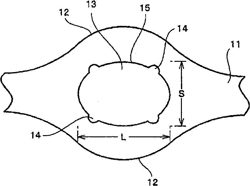
[0051] Figure 10 The connector of the shown embodiment 3 is provided in the outlet side form of the embedded hole 13 of the belt support rod 11 expansion part 12 in the belt connection member 4 and the form of the expansion part 22 of the spring hook 5 is different from the structure of the above-mentioned embodiment 1. The locked portion 15 provided on the exit side of the fitting hole 13 of the expansion portion 12 of the belt support rod 11, that is, the major axis L and the minor axis S are as follows in the above-mentioned embodiment 1. figure 2 , 3 As shown, the major axis L of the fitting hole 13 and the major axis L' of the enlarged portion 22 are formed to have the same length, but in Embodiment 3, the oblate circle (including the ellipse) formed by the major axis L and the minor axis S ) to form the embedding hole 13, the enlarged part 22 of the spring hook 5 is formed by the major axis L' and the minor axis S' which are larger than the major axis L and the minor ...
PUM
 Abstract
Description
Claims
Application Information
 - R&D Engineer
- R&D Manager
- IP Professional
- Industry Leading Data Capabilities
- Powerful AI technology
- Patent DNA Extraction
Browse by: Latest US Patents, China's latest patents, Technical Efficacy Thesaurus, Application Domain, Technology Topic, Popular Technical Reports.
© 2024 PatSnap. All rights reserved.Legal|Privacy policy|Modern Slavery Act Transparency Statement|Sitemap|About US| Contact US: help@patsnap.com


