
Electric connector

A technology of electrical connectors and contact parts, which is applied in the direction of connection, circuit, and parts of connection devices, etc., and can solve problems such as incompatibilities with low-height electrical connectors

Inactive Publication Date: 2015-07-29
蔡周贤
View PDF0 Cites 2 Cited by
  • Summary
  • Abstract
  • Description
  • Claims
  • Application Information

AI Technical Summary

Problems solved by technology

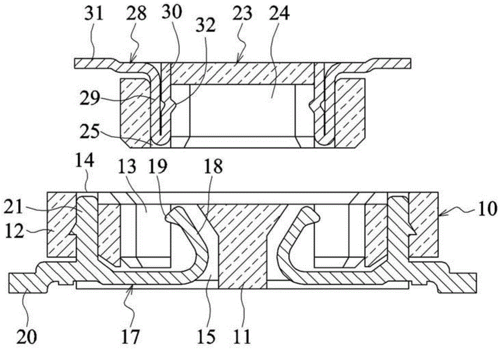
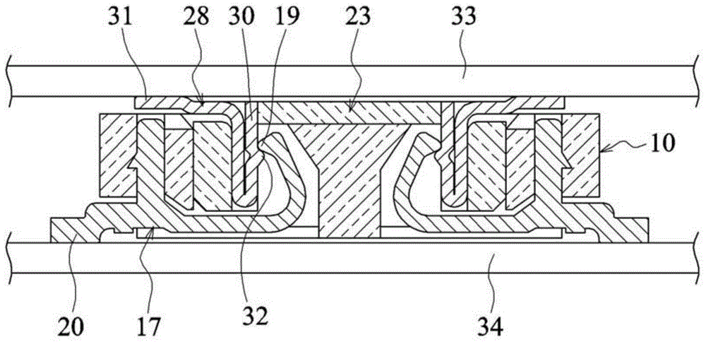
[0009] 1. The fixing parts 29 and 21 of the male and female terminals are vertically fixed to the male and female base bodies 23 and 10. However, in order to make the electronics thin and short, the above design does not meet the requirements of low-height electrical connectors

Method used


Image

  • Electric connector
  • Electric connector
  • Electric connector

Examples


Embodiment Construction

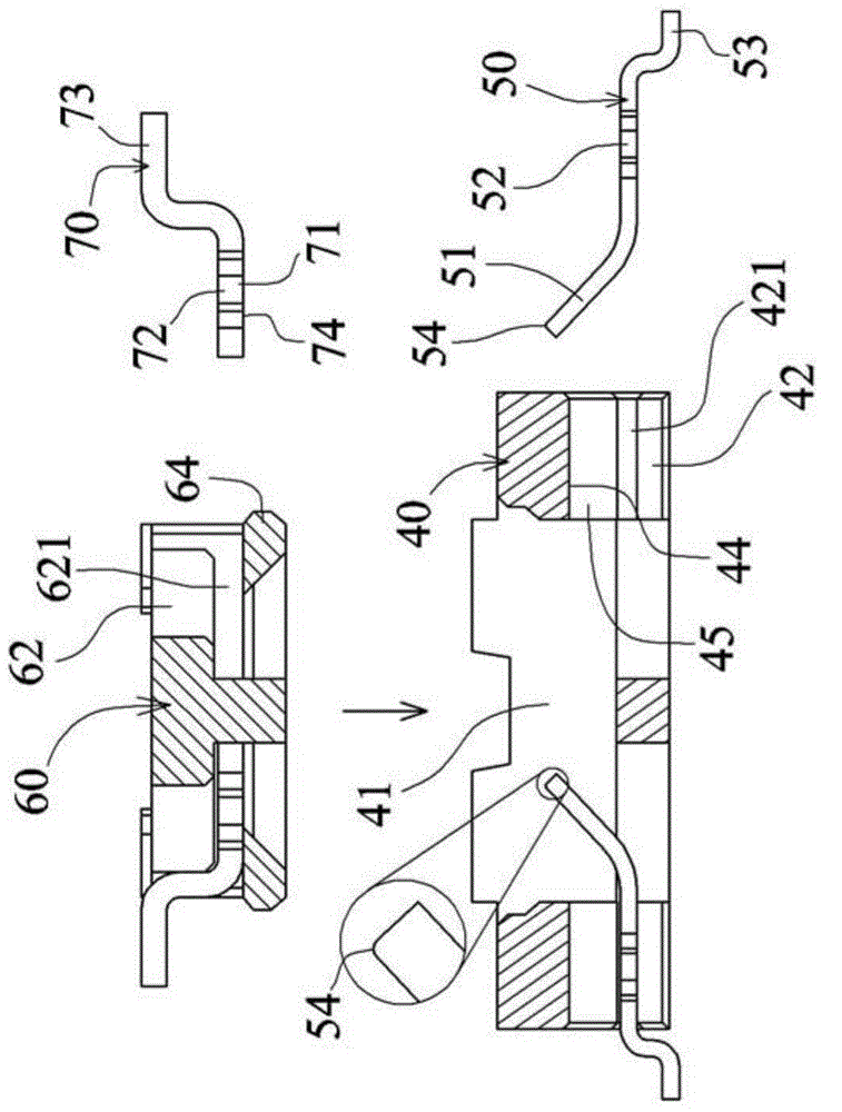
[0112] see image 3 , Figure 4 and Figure 5 , is the first embodiment of the present invention, which is a board-to-board electrical connector, which includes a female base body 40, a plurality of female terminals 50, a male base body 70, a plurality of male terminals 80, and 4 female soldering pieces 80, 4 public soldering pieces 85, and a locking device, wherein:

[0113] The female seat body 40 is made of insulating plastic material and a recessed socket groove 41 is formed in the middle. The socket groove 41 is a single groove. Terminal groove 42, the female terminal groove 42 is provided with a horizontal and horizontal fixing groove 421, the top of the fixing groove 421 is a concave portion 45 inserted in the horizontal direction, the concave portion 45 is provided with an upper card surface 44, and the female base body 40 is a The two outer ends of a row of female terminal grooves 42 on the side are respectively provided with a groove 49 from top to bottom. The fi...


PUM


Abstract

An electrical connector comprises a female base formed with a fitting slot; female terminals each arranged on one side of the female base and made of a metal sheet and integrally formed with an extension having a contact disposed in the fitting slot, a fixing portion fixed to the female base and a pin extending out of the female base; a male base mounted in the fitting slot; and male terminals each arranged on one side of the male base and made of a metal sheet and integrally formed with an extension having a contact elastically resting against the contact of the female terminal, a fixing portion fixed to the male base and a pin extending out of the male base. One of the male and female terminals is formed by bending a plate surface, and the fixing portions thereof are transversally fixed.

Description

technical field [0001] The present invention relates to an electrical connector, in particular to a board-to-board electrical connector and an electrical connector in which spring terminals are embedded in a plastic seat and integrally injection-molded. Background technique [0002] see figure 1 and figure 2 , is a known board-to-board electrical connector, which is provided with a male and a female electrical connector that are nested in each other to electrically connect two circuit boards, and it includes: [0003] A female seat body 10, which is provided with a middle part 11 and a peripheral side part 12, the middle part 11 and the peripheral side part 12 form two concave parts 13, the peripheral side part 12 is provided with female terminal fixing grooves 14 arranged at intervals, the middle part 11 There are female terminal movable grooves 15 arranged at intervals on both sides. [0004] A plurality of female terminals 17, which are assembled on the female base bo...

Claims


Application Information

Patent Timeline
Patent Type & Authority Applications(China)
IPC IPC(8): H01R13/24H01R13/405
CPCH01R12/73H01R12/716
Inventor 蔡周贤
Owner 蔡周贤
Learn More