


Quick Research
Generate reliable direction feasibility study reports for your R&D in just a few steps.

Technical Q&A
Discover and master advanced knowledge NOW. Basics, ideas, possibilities, all at once.

Find Solutions
As an expert in R&D theories, this can generate solutions to your technical problems instantly.

Evaluate Feasibility
Analyze your overall solution with one click, know your potential R&D risks in advance.

Monitor Landscape
Get weekly tech updates, stay abreast of the latest tech innovations and key insights.
High resolution ratio digital holographic image capturing device
A digital holographic, high-resolution technology, which is applied in the field of digital holography, can solve the problems of low resolution and small field of view of digital holographic reproduction images, and achieve the purpose of increasing the area of holograms, increasing the field of view, and improving digital holographic reproduction images. The effect of resolution
- Summary
- Abstract
- Description
- Claims
- Application Information
AI Technical Summary
Problems solved by technology
Method used
Image

Examples
Embodiment 1
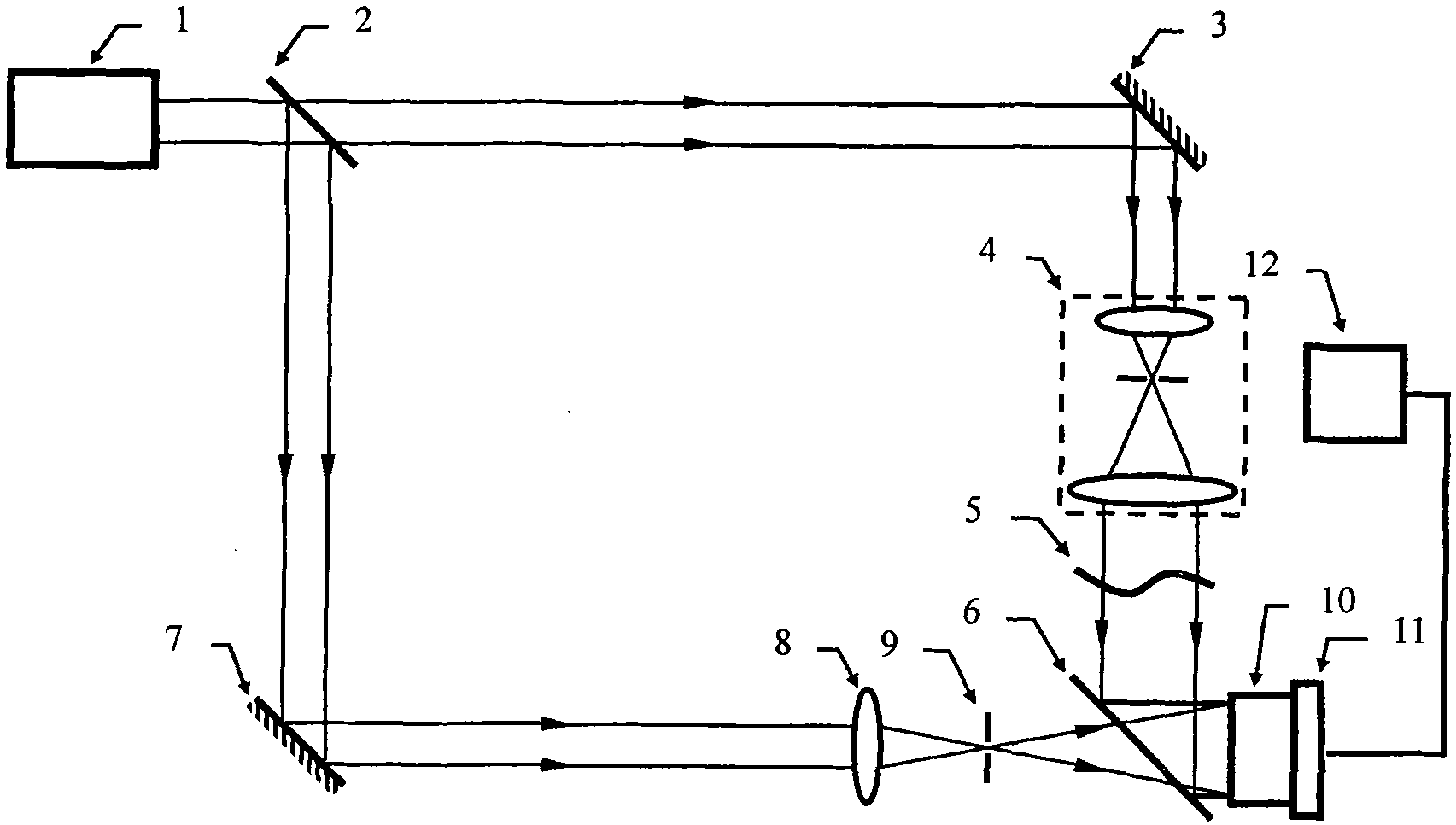
[0021] Device Example 1: See figure 1 , the acquisition device of the high-resolution digital hologram includes a helium-neon laser 1, a beam splitter 2, a first total reflection mirror 3, a second total reflection mirror 7, a beam expander collimator 4, the same Product 5, a beam expander 8, a pinhole 9, a semi-transparent and semi-reflective mirror 6, a linear array CCD 10, a micro-displacement platform 11 capable of moving in two-dimensional directions, and a computer 12.
[0022] Wherein, the beam splitter 2 is an adjustable splitting ratio beam splitter, which is arranged on the optical path of the beam emitted by the He-Ne laser 1, and can split the beam into a first beam and a second beam. The first total reflection mirror 3 is arranged on the optical path of the first beam, and reflects the first beam to the beam expander and collimator 4 . After the first light beam is expanded and collimated into parallel light by the beam expander and collimator 4 , it irradiates t...
Embodiment 2
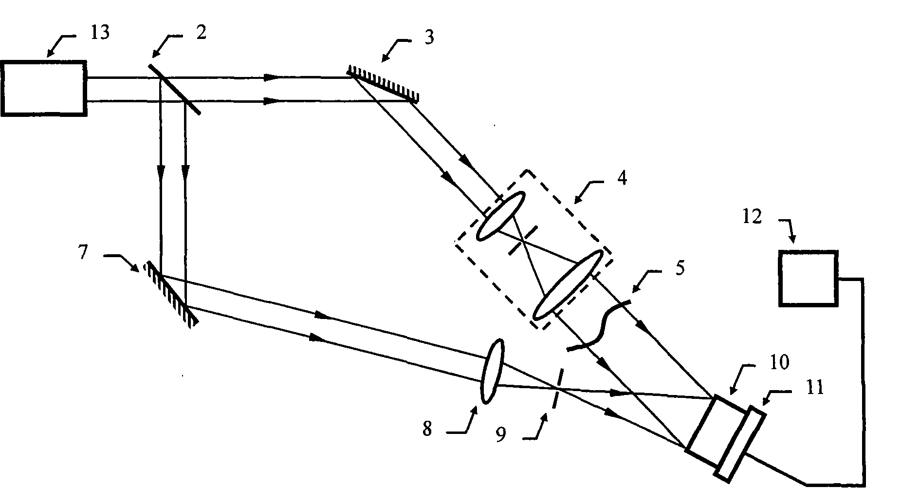
[0032] Device embodiment 2: see figure 2 The acquisition method and device of the high-resolution digital hologram include a semiconductor laser 13, a beam splitter 2, a first total reflection mirror 3, a second total reflection mirror 7, a beam expander collimator 4, A sample 5 , a beam expander 8 , a pinhole 9 , a linear CCD 10 , a two-dimensionally movable micro-displacement platform 11 , and a computer 12 .
[0033] Will figure 2 The second embodiment shown with figure 1 Comparing the first embodiment shown, it can be found that the first light beam as the object light and the second light beam as the reference light formed by the semiconductor laser 13 have not undergone the transflective and semi-reflective process described in the first embodiment of the present invention. mirror 6, and the interference occurs directly. The formed interference fringes are collected by the linear array CCD 10 in the interference area through the movement of the micro-displacement pl...
Embodiment 3
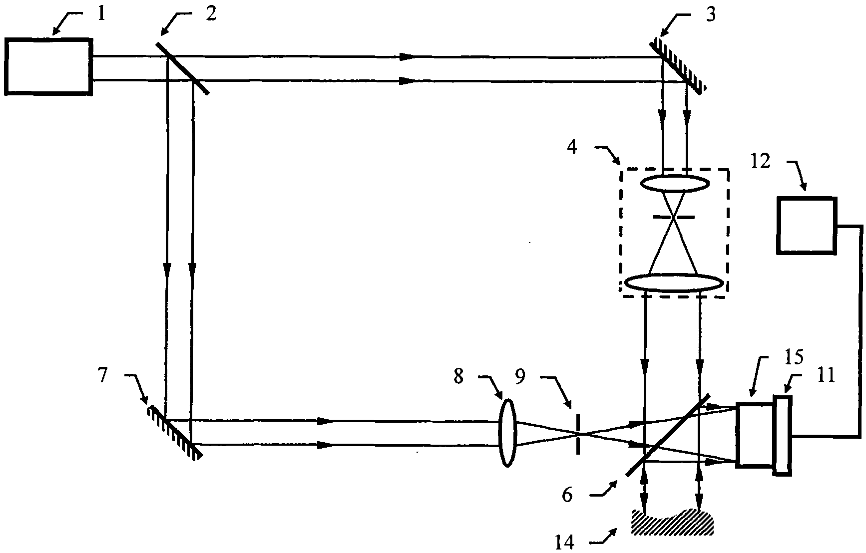
[0034] Device embodiment 3: see image 3 The acquisition method and device of the high-resolution digital hologram include a helium-neon laser 1, a beam splitter 2, a first total reflection mirror 3, a second total reflection mirror 7, a beam expander collimator 4 , a sample 14, a microscope objective lens 8, a pinhole 9, a half-transparent mirror 6, a line-array CCD combination 15, a two-dimensionally movable micro-displacement platform 11, and a computer 12.
[0035] Will image 3 Comparing the embodiment shown with the embodiment 1 shown in the figure, it can be found that the first total reflection mirror 2 is arranged on the optical path of the first light beam, and reflects the first light beam to the beam expander collimator 4 . The first light beam is expanded and collimated into parallel light by the beam expander and collimator 4 , passes through the half mirror 6 , and then irradiates the sample 14 . The first light beam reflected from the sample 14 is emitted to...
PUM
 Abstract
Description
Claims
Application Information
 - R&D Engineer
- R&D Manager
- IP Professional
- Industry Leading Data Capabilities
- Powerful AI technology
- Patent DNA Extraction
Browse by: Latest US Patents, China's latest patents, Technical Efficacy Thesaurus, Application Domain, Technology Topic, Popular Technical Reports.
© 2024 PatSnap. All rights reserved.Legal|Privacy policy|Modern Slavery Act Transparency Statement|Sitemap|About US| Contact US: help@patsnap.com