
Bimetallic composite wire rod high-efficient production line

A composite wire and production line technology, applied to other manufacturing equipment/tools, instruments, computer control, etc., can solve the problems of lower product production efficiency, long downtime, copper strip drilling, etc., to improve production efficiency and reduce production costs , metallurgical bonding firm effect

Inactive Publication Date: 2008-02-13
费兰英 +2
View PDF0 Cites 23 Cited by
  • Summary
  • Abstract
  • Description
  • Claims
  • Application Information

AI Technical Summary

Problems solved by technology

[0003] 1. Since the copper strips are mounted on the material rack in coils, and each coil is only a few hundred meters long, after welding a coil of copper coils or aluminum rods, it is necessary to stop the machine and change another coil of copper coils or aluminum rods to ensure that the cladding welding The production process cannot be carried out continuously, and the downtime is long, which reduces the production efficiency of the wire blank, and at the same time cannot produce large and heavy bimetal composite wire blanks;
[0004] 2. The alkaline water soaking surface pretreatment method of aluminum rods is backward, the labor intensity of workers is high and the quality is greatly affected by human factors. If the oxides on the aluminum rods are not completely removed, the metallurgical combination of copper and aluminum will be seriously affected , resulting in a low yield of products, and alkaline water waste and residues must be treated to meet environmental protection requirements, increasing production costs;
[0005] 3. The welding current of the argon arc welding machine and the driving speed of the overmolding machine are independent of each other and not related to each other. The welding current cannot be adjusted in time with the change of the driving speed of the overmolding machine. At the welding seam, due to the relatively slow driving speed and the relatively high current of the argon arc welding machine, the copper strip is perforated, resulting in the interruption of continuous production;
[0006] 4. It is impossible to monitor the burning condition of the tungsten electrode in real time, so that the argon arc welding machine cannot use a large welding current, and the welding speed of the wire blank is low (only 5-7m can be welded per minute), which further reduces the production efficiency of the product

Method used


Image

  • Bimetallic composite wire rod high-efficient production line
  • Bimetallic composite wire rod high-efficient production line
  • Bimetallic composite wire rod high-efficient production line

Examples


Embodiment 1

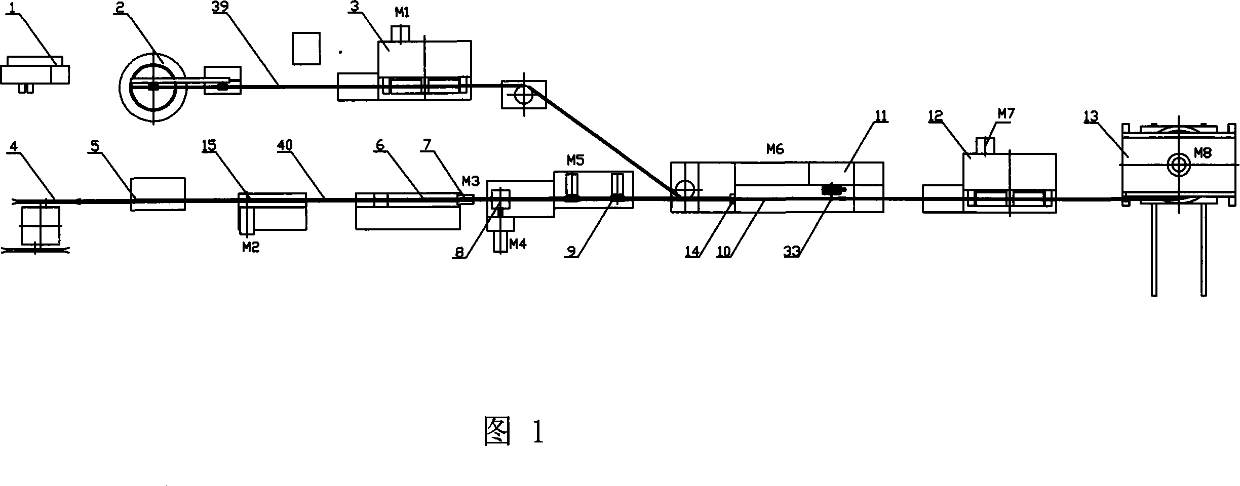
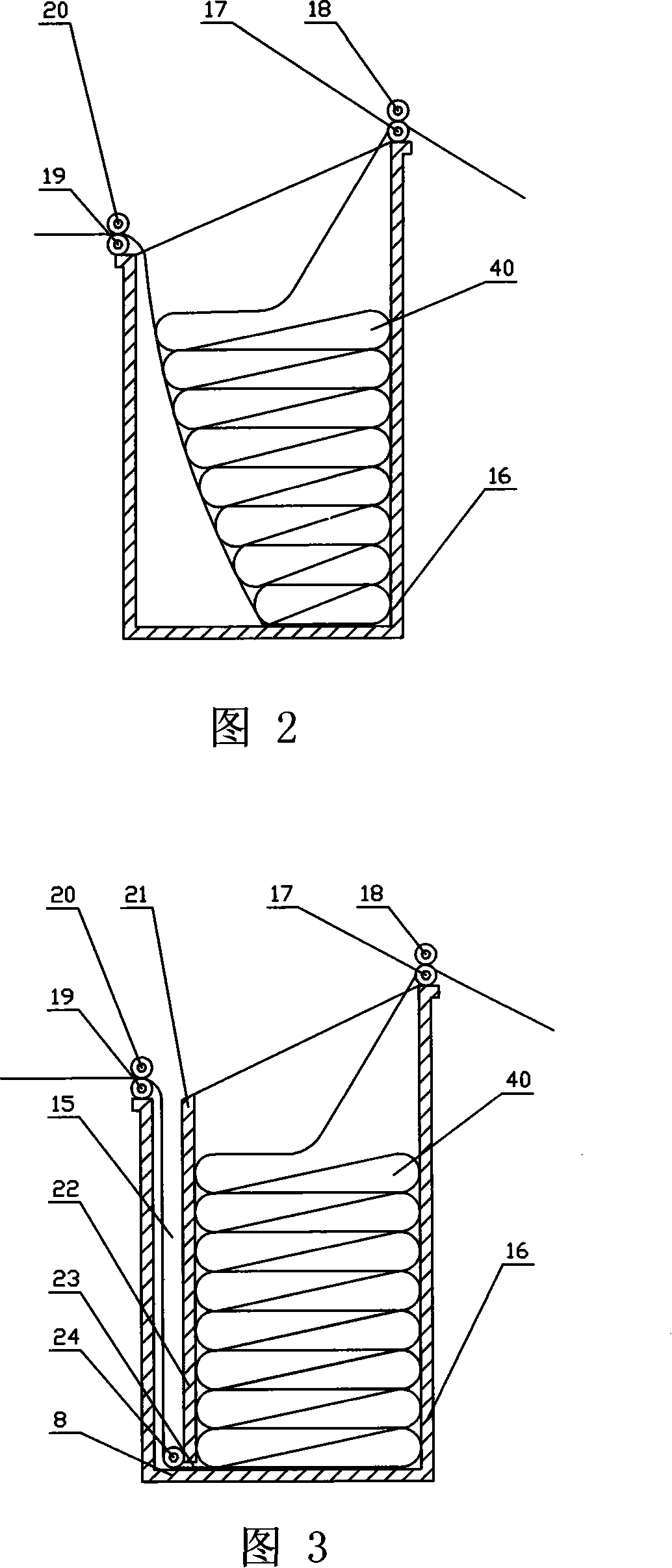
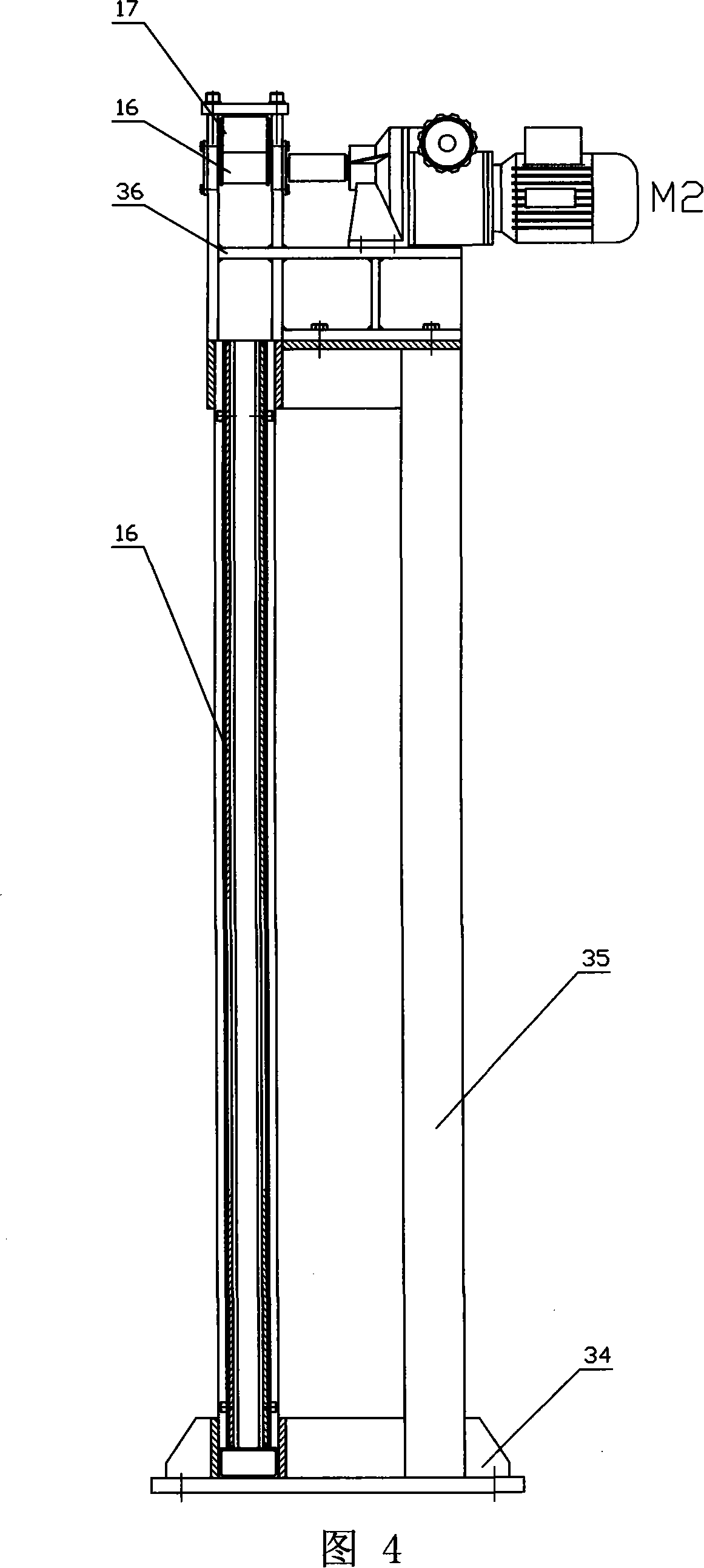
[0026] As shown in Figure 1: there are aluminum rod butt welding machine 1 (resistance butt welding machine), aluminum rod discharging rack 2, and aluminum rod drawing machine 3 which are arranged in sequence, which are the same as the prior art; There are copper strip unloading rack 4 with the same technology, copper strip butt joint machine 5 (TIG argon arc welding machine), copper strip cleaning tank 6, copper strip drying machine 7, copper strip grinding machine 9 and overmolding machine arranged in sequence 10. Welding device 11, composite wire billet drawing machine 12, wire take-up machine 13, etc. An aluminum rod peeling device 14 is provided between the aluminum rod drawing machine 3 and the overmolding machine 10, and the copper strip butt joint machine 5 and A copper tape storehouse 15 is arranged between the copper tape cleaning tanks 6 . Aluminum rod peeling device 14 is as shown in Figure 5: can be separately arranged or be installed in the die hole of the inner ...

Embodiment 2

[0028] As shown in Figure 1: other is identical with embodiment 1, just is provided with copper strip trimming machine 8 between copper strip drying machine 7 and copper strip grinding machine 9, so that copper strip is more orderly, standard. And copper strip warehouse 15 as shown in Figure 3: be on the basis of embodiment 1, be provided with vertical dividing plate 21 in box-shaped warehouse body 16, between the bottom plate 22 of vertical dividing plate 21 and box-shaped warehouse body 16 There is a guide opening 23 between them, and a guide wheel 24 is arranged at the guide opening 23 .

Embodiment 3

[0030] As shown in Figure 6, on the basis of Embodiment 1, a PLC control unit such as a single-chip microcomputer or a computer is provided, that is, a single-chip microcomputer IC1 is provided, and the output of the single-chip microcomputer IC1 is passed through a frequency converter 25, a frequency converter 26, a frequency converter 28, and a frequency converter respectively. 29, frequency converter 30, frequency converter 31, frequency converter 32 and aluminum rod drawing machine motor M1, copper tape library motor M2, copper tape drying machine motor M3, copper tape grinding machine M5, overmolding machine drive motor M6 , composite wire billet drawing machine motor M7, take-up machine M8 join; the output of described single-chip microcomputer IC1 joins with welding device 11, and the output of welding device 11 joins with welding torch through current transformer, and the output end of current transformer Connect with the input terminal of the single-chip microcomputer ...


PUM


Abstract

The invention discloses a high-efficiency production line for bimetallic composite wires, which comprises an aluminum rod butt welding machine (1), an aluminum rod discharging rack (2), and an aluminum rod drawing machine (3) arranged in sequence; and a copper strip discharging machine arranged in sequence frame (4), copper strip butt joint machine (5), copper strip cleaning tank (6), copper strip drying machine (7), copper strip grinding machine (9) and overmolding machine (10) arranged in sequence, welding device (11), composite wire billet drawing machine (12), wire take-up machine (13); an aluminum bar peeling device ( 14), a copper strip warehouse (15) is provided between the copper strip butt joint machine (5) and the copper strip cleaning tank (6), which can reduce the labor intensity of workers, ensure continuous production and increase the yield of finished products.

Description

Technical field: [0001] The invention relates to production equipment for bimetallic composite wires such as copper-clad aluminum and copper-clad steel, in particular to a high-efficiency production line for bimetallic composite wires that can reduce labor intensity of workers, ensure continuous production, and increase yield. Background technique: [0002] At present, the production method of copper-clad aluminum, copper-clad steel and other bimetallic composite wire blanks is mainly the cladding welding-drawing method. The specific production method is to pull the aluminum rod (steel rod) through the aluminum rod drawing machine, and then manually degrease the drawn aluminum rod with alkaline water soaking, and finally wrap the aluminum rod around the aluminum rod for feeding. At the same time, the copper strip on the copper strip discharge rack is pretreated through the cleaning tank, copper strip drying machine, copper strip trimming machine, and copper strip grinding ma...

Claims


Application Information

Patent Timeline
IPC IPC(8): B23P23/06B21C37/04G05B19/042
Inventor 戴雅康王玉凯林波费兰英刘少良
Owner 费兰英
Learn More