
Method for preparing samming board

A manufacturing method and technology of uniform temperature plates, which are applied in heat exchange equipment and other directions, can solve problems such as difficulties in practical operation of processing procedures, collapse, channel deflection, etc.

Inactive Publication Date: 2008-02-06
JIEFEI
View PDF0 Cites 13 Cited by
  • Summary
  • Abstract
  • Description
  • Claims
  • Application Information

AI Technical Summary

Problems solved by technology

Regardless of whether the heat dissipation plate heat pipe formed by the above-mentioned prior art can effectively achieve the above-mentioned heat dissipation effect, there are difficulties in practical operation in this processing procedure.
First of all, the cooling plate has to face the processing process of the heat conduction channel, and the precision must be paid attention to when opening the heat conduction channel. If the opening angle is slightly deviated, the entire channel will be deflected, and defective products may also be caused (such as the surface of the heat sink is collapsed). , plus the number of heat conduction channels is quite large, so the probability of error is relatively increased, and the probability of mass production is not high

Method used


Image

  • Method for preparing samming board
  • Method for preparing samming board
  • Method for preparing samming board

Examples


Embodiment Construction

[0025] In order to further understand the features and technical contents of the present invention, please refer to the following detailed description and accompanying drawings of the present invention. However, the attached drawings are only for reference and illustration, and are not intended to limit the present invention.

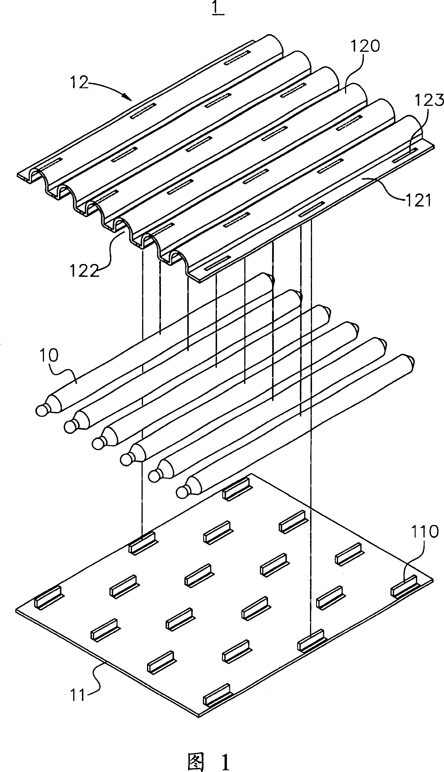
[0026] Fig. 1 is an exploded schematic diagram of a temperature chamber of the present invention. The invention provides a method for manufacturing a vapor chamber, the steps of which are as follows:

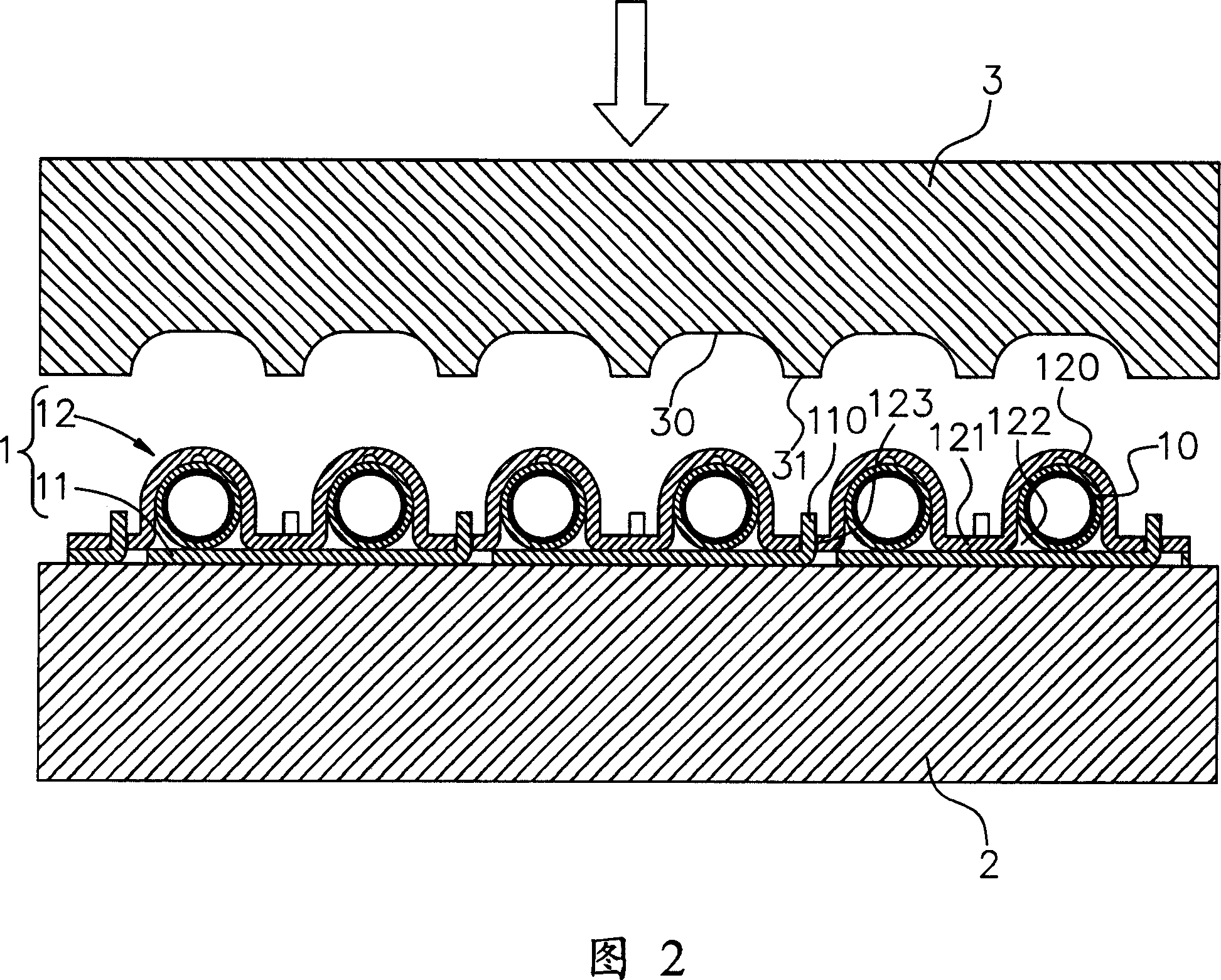
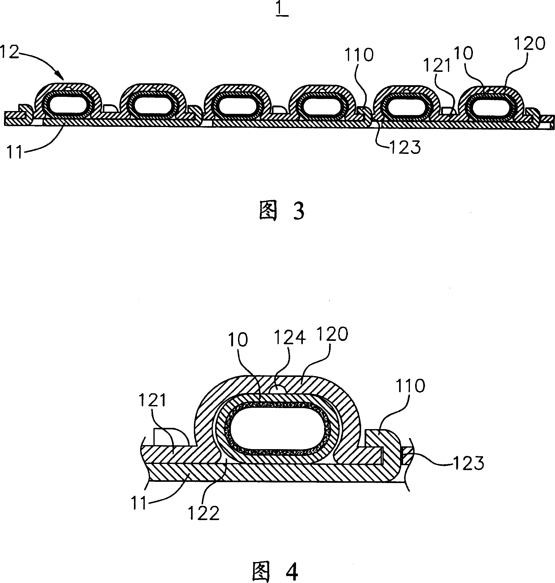
[0027] Firstly, a plurality of heat pipes 10 , the first plate body 11 and the second plate body 12 required to form the vapor chamber 1 are prepared. The first and second plates 11, 12 are made of materials with good thermal conductivity, such as aluminum, copper, etc., and are flat plates; the second plate 12 is further stamped and formed with a plurality of The covers 120 are in the shape of a straight line and are recessed from the bottom surface of ...


PUM


Abstract

The invention relates to a manufacturing method of a uniform temperature plate, the steps of which is that: first, a plurality of heat pipes, a first plate body and a second plate body are prepared, wherein, a plurality of covers which is recessed into the end face of the second plate body and extruded from the superface of the second plate body are punch formed on the second plate body; a recess area formed by various covers is provided with cambered spaces which can hold the heat pipes horizontally; second, the heat pipes are respectively arranged in the cambered spaces; the first plate body is attached on the end face of the second plate body to make the two plate bodies overlapped up and down; third, an external force is applied on the second plate body for a compact surface contact formed in the extruding direction by the heat pipes and the corresponding cambered spaces of the heat pipes.

Description

technical field [0001] The invention relates to a method for manufacturing a vapor chamber, in particular to a manufacturing method of a vapor chamber that utilizes two plate bodies to clamp a plurality of heat pipes, and through pressing, the two plate bodies and the heat pipes are combined more tightly. method. Background technique [0002] In the prior art, there is a "manufacturing method of a heat sink heat pipe", which discloses a method that "includes processing the heat sink to set a plurality of heat conduction channels that are not connected at the ends; The process of sealing the open end and retaining at least one open end; simultaneously filling the working fluid and vacuuming the process from the retained open end, and then sealing it” method. Its purpose is mainly to use the material (such as copper and aluminum) with better thermal conductivity of the cooling plate, cooperate with the so-called processing method to form a heat conduction channel, and implant...

Claims


Application Information

Patent Timeline
IPC IPC(8): B21D53/08B23P15/26
Inventor 徐惠群
Owner JIEFEI
Learn More