
Double groove conjoined angular contact ball bearing

An angular contact ball bearing and one-piece technology, which is applied in the field of radial angular contact ball bearings, inertial instruments, and double-groove conjoined angular contact ball bearings, can solve the problem of difficult product qualification rate guarantee, unstable rotation of the rotating system, and Shaft position instability and other problems, to achieve the effect of reducing assembly difficulty, increasing processing difficulty, and fewer types of parts

Inactive Publication Date: 2008-01-30
CHONGQING HUAYU ELECTRIC GRP
View PDF1 Cites 3 Cited by
  • Summary
  • Abstract
  • Description
  • Claims
  • Application Information

AI Technical Summary

Problems solved by technology

[0002] In the prior art, the rotating shaft system of high-precision instruments with high speed is generally realized by angular contact bearings installed in pairs. Since the shaft system consists of many parts, its assembly is complicated and has a great impact on its accuracy.
That is, due to the manufacturing error of the shafting installation base and the manufacturing error of each part composed of the shafting, after being combined together, the cumulative error formed will reduce the combination accuracy of the shafting, make the position of the rotating shaft of the shafting unstable, and cause the entire rotation The system does not rotate smoothly and generates vibrations, which reduces the accuracy of the instrument and shortens its service life
Chinese Patent ZL200520033268.1 "Dynamic Adjustable Gyroscope Integrated Drive Shaft Assembly" In order to simplify the mechanical structure of the drive shaft assembly and improve the stability of the reference axis, the inner ring is changed to an integral structure, but this will inevitably increase the processing time. Difficulty, the pass rate of the product is difficult to be guaranteed; at the same time, there is still the problem of inconvenient adjustment

Method used


Image

  • Double groove conjoined angular contact ball bearing

Examples


Embodiment Construction

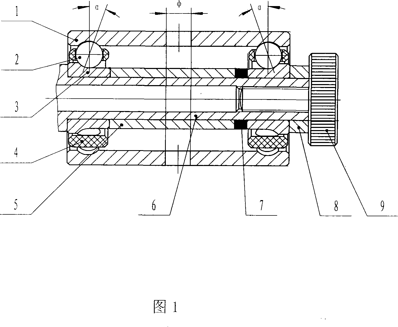
[0013] As shown in Figure 1, a double-groove conjoined angular contact ball bearing includes a bearing outer ring 1, two rows of bearing steel balls 2, two bearing inner rings 3, two cages 4, and an inner ring bushing 5 And an adjusting washer 7, there is an annular raceway at both ends of the bearing outer ring 1, corresponding to the raceways of the two bearing inner rings, and forming a contact angle α; the inner ring bushing 5, the shaft 6 shoulder and the adjustment The washer 7 locks the inner ring 3 of the bearing, and the required preload of the bearing can be achieved by adjusting the thickness of the washer 7 . Axle 6, process washer 8 and process screw 9 form the detachable conjoined bearing. There is a through hole φ in the radial center of the outer ring of the bearing, which is used to feel or test the axial preload of the bearing.

[0014] The material of the cage 4 can be metal or non-metal as required. Shaft 6 can be used as a drive shaft or a process shaft,...


PUM


Abstract

The invention provides a double-groove siamesed edge-contact spherical bearing, comprising an outer bearing ring, two arrays of bearing beads, two inner bearing rings, two support stands, an inner ring bushing, and a regulation gasket. Both ends of the outer bearing ring are respectively provided with a ring rolling channel corresponding with rolling channels of the two inner bearing rings, and form a contact angle; the inner ring bushing, a shoulder and the regulation gasket lock the inner bearing rings; the invention is assembled by a shaft, a craft gasket and craft screws into a detachable siamesed bearing. The invention adopts siamesed outer bearing rings, which can increase such size and position requirements as concentricity and perpendicularity of the shaft system, and endows the bearing with high precision, thus prolonging the service life of the bearings without increasing the working difficulty. The invention also has the advantages of simple structure, being convenient to be arranged, and adjustable axial preload and so on.

Description

technical field [0001] The invention relates to a centripetal angular contact ball bearing, in particular to a double-groove conjoined angular contact ball bearing, which is especially suitable for inertial instruments with high precision and high rotational speed, such as dynamic tuning gyroscopes. It belongs to the field of machinery manufacturing. Background technique [0002] In the prior art, the rotating shaft system of high-precision instruments with high speed is generally realized by angular contact bearings installed in pairs. Since the shaft system consists of many parts, its assembly is complicated and has a great impact on its accuracy. . That is, due to the manufacturing error of the shafting installation base and the manufacturing error of each part composed of the shafting, after being combined together, the cumulative error formed will reduce the combination accuracy of the shafting, make the position of the rotating shaft of the shafting unstable, and caus...

Claims


Application Information

Patent Timeline
IPC IPC(8): F16C19/18F16C33/58
Inventor 夏明泽林萍
Owner CHONGQING HUAYU ELECTRIC GRP
Learn More