Roller brake testing dynamometer

A technology of braking test and braking force, which is applied in the direction of measuring devices, vehicle testing, automobile tire testing, etc., can solve the problems of high complexity, cost, complex structure and configuration of the dynamometer, etc., and achieve reduced sensitivity and complex structure and the effect of expensive cost reduction

Inactive Publication Date: 2012-07-18
SNAP ON EQUIP
View PDF0 Cites 0 Cited by
  • Summary
  • Abstract
  • Description
  • Claims
  • Application Information

AI Technical Summary

Problems solved by technology

[0003] The construction and arrangement of known dynamometers with sensing rollers of this type are complex and expensive
The determination of the rotational speed of the driven vehicle tires is carried out by sensing rollers, an operation that requires a highly complex and expensive sensing system and includes an evaluation or control action that is sensitive to faults

Method used


Image

  • Roller brake testing dynamometer
  • Roller brake testing dynamometer
  • Roller brake testing dynamometer

Examples


Embodiment Construction

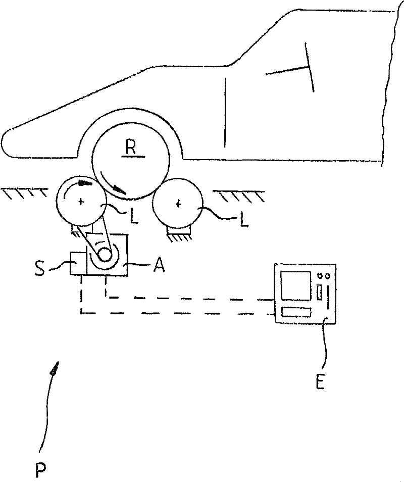
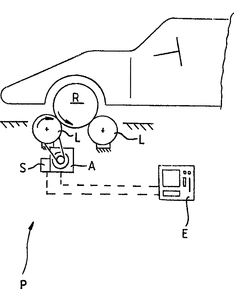
[0019] figure 1 is a side view of the setup where the wheels R of the vehicle rest on the two rollers L of the dynamometer P. figure 1 The drum L shown on the left side of is driven by the driver A shown in the figure to drive the tire R of the vehicle to rotate. In addition, a braking force sensor S is provided, which determines in a known manner the required driving force of the left-hand pulley L, or the resistance in the opposite direction.

[0020] The brake force sensor S and the drive A are connected to the evaluation and control unit E. Based on the input signal from the brake force sensor S, the control unit E outputs a control signal, which in particular includes a signal for switching off the drive A.

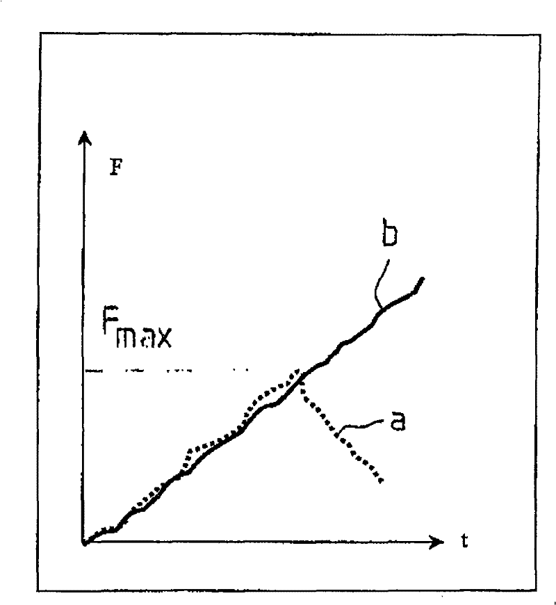
[0021] figure 2 A diagram showing the braking force profile of two vehicle tires being measured simultaneously in the braking test procedure described. In this case, the solid line "b" represents the graph of the braking force of the second tire as a function of...


PUM


Abstract

The present invention relates to a roller brake testing dynamometer (P) for vehicles whose braking forces are to be ascertained, wherein there is provided at least one roller (L) which is driven by way of a drive (A) in order in turn to drive a vehicle tyre (R) bearing against the roller (L), wherein there is provided at least one braking force sensor (S) for ascertaining a braking force exerted on the roller (L) by the tyre (R), and wherein there is provided an evaluation and control unit (E) to which the signals of the braking force sensor (S) can be fed. Furthermore, it is provided that the evaluation and control unit (E) is adapted on the basis of the signals from the braking force sensor (S) to ascertain the transition from static friction to sliding friction between the tyre (R) andthe roller (L) independently of the speed of rotation of the roller.

Description

technical field [0001] The invention relates to a dynamometer for a roller brake test of a vehicle for determining the braking force of a vehicle according to the preamble of claim 1 . Background technique [0002] Roller brake test dynamometers of this type have long been known in the art from the prior art. Typically, such dynamometers have two rollers arranged in parallel on which the vehicle to be tested moves. During the test, the vehicle tires are on or between the rollers. When driven into the dynamometer, the vehicle tires touch a so-called sensing roller, which is resiliently supported by a switch that initiates the operation of a brake test when the wheel is loaded on it. Among other things, this sensing roller can also be used to record the rotational speed of a wheel driven by one of the two rollers and provide this to the evaluation station. At the same time the rotational speed of the drive drum is also monitored. As soon as the rotational speed of the incr...

Claims


Application Information

Patent Timeline
Patent Type & Authority Patents(China)
IPC IPC(8): G01L5/28G01M17/02
CPCG01L5/288G01M17/0074G01L5/282
Inventor E·塞贝尔
Owner SNAP ON EQUIP
Why Eureka
Try Eureka