A flow rate detector for water conservancy measurement

A detector and flow rate technology, applied in the field of flow rate detectors for water conservancy measurement, can solve the problems of inaccurate data, long response time, no comparison data, etc., to achieve the effect of ensuring positioning, ensuring water conservancy measurement, and protecting deformation

Active Publication Date: 2021-06-08
SICHUAN UNIV
View PDF15 Cites 0 Cited by
  • Summary
  • Abstract
  • Description
  • Claims
  • Application Information

AI Technical Summary

Problems solved by technology

[0007] Aiming at the deficiencies of the prior art, the present invention provides a flow velocity detector for water conservancy measurement, which overcomes the deficiencies of the prior art, has a reasonable design and a compact structure, and aims to solve the problem that the existing flow velocity detectors are all detected by a single sensor. The flow rate of water requires a long response time, and the data is not accurate; at the same time, there is no comparison data, and the results cannot be applied to the problem of water conservancy construction

Method used


Image

  • A flow rate detector for water conservancy measurement
  • A flow rate detector for water conservancy measurement
  • A flow rate detector for water conservancy measurement

Examples


Embodiment 1

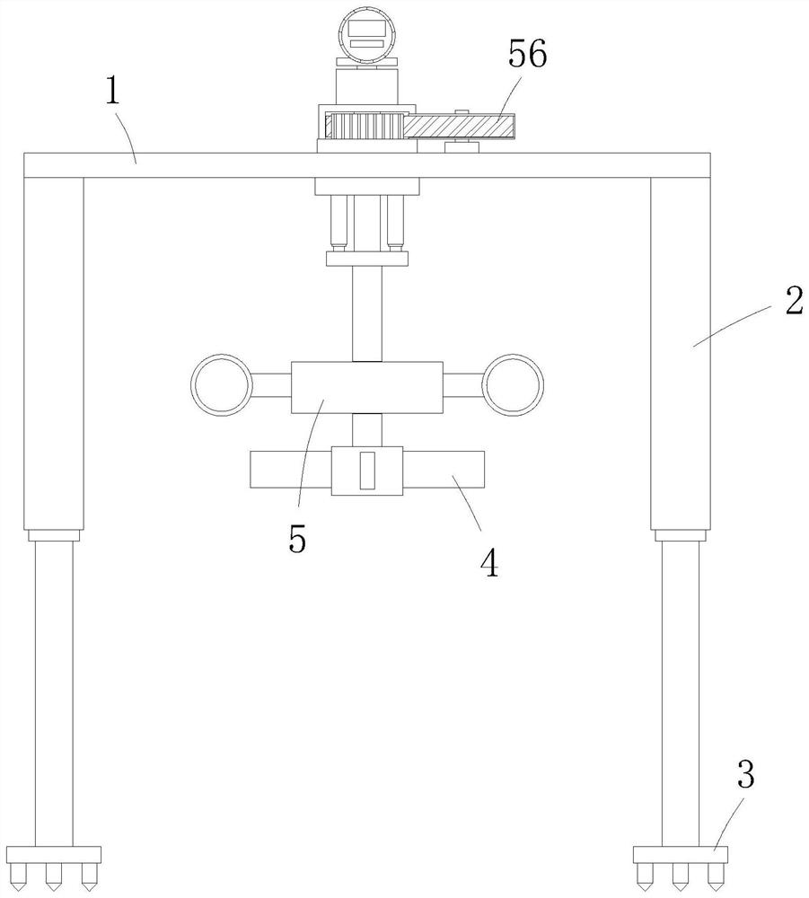
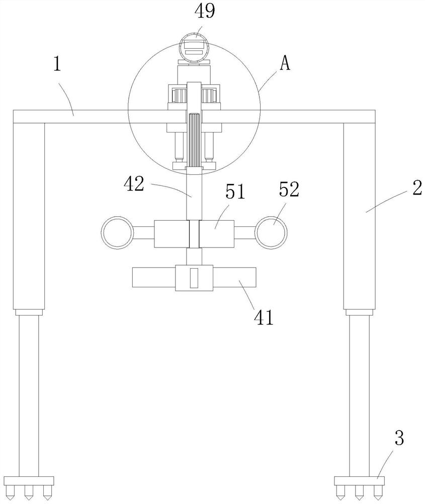
[0035] A flow rate detector for water conservancy measurement, comprising a horizontally arranged frame 1, four electric telescopic legs 2 are fixedly installed on the lower end edge of the frame 1, and fixed nail plates are fixedly installed on the telescopic ends of the electric telescopic legs 2 3. When the detector enters the water, the electric telescopic legs 2 extend downward to position the fixed nail plate 3 on the bottom of the water, so as to achieve accurate measurement. The lower end of the frame 1 is provided with a flow rate measurement mechanism 4 and a flow rate correction mechanism 5. The flow velocity measuring mechanism 4 is used to measure the water flow velocity in the river channel or canal, and the flow velocity correction mechanism 5 is used to assist measurement and give data, which is calibrated in combination with the flow velocity of the flow velocity measuring mechanism 4, so as to ensure accurate measurement;

[0036] In this example, if Figure ...

Embodiment 2

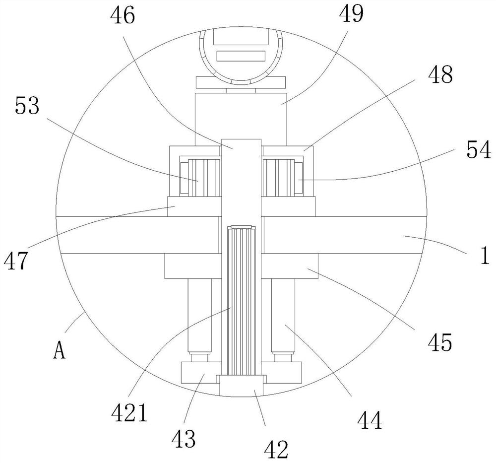
[0043] The difference between this embodiment and embodiment 1 is that, as image 3 As shown, the upper end of the drive shaft 42 is covered with a lifting plate 43, and the upper edge of the lifting plate 43 is connected with the lower plate 45 through a plurality of oil cylinders 44. Through the synchronous start and stop of a plurality of oil cylinders 44, the liquid level can be adjusted. The detection of water flow velocity at different liquid levels can meet the needs of water conservancy measurement.

[0044] In this example, if image 3 As shown, a plurality of the oil cylinders 44 are distributed in an annular array, and the number of the oil cylinders 44 is more than or equal to three, effectively ensuring the movement of the rotating impeller 41 and the plastic moving block 51. At the same time, the annular arrangement of the oil cylinders 44 can effectively Ensure the positioning of the drive shaft 42 and the sleeve shaft 46, and the protection device will not be ...


PUM


Abstract

The present invention relates to the technical field of water conservancy measurement, and provides a novel flow velocity detector for water conservancy measurement, aiming to solve the problem that the existing flow velocity detectors only detect the flow velocity of water through sensors, which require a long response time and inaccurate data; At the same time, there is no comparison data, and the results cannot be applied to the problems of water conservancy construction, including 1. The frame set horizontally, four electric telescopic legs are fixedly installed on the lower edge of the frame, and the telescopic ends of the electric telescopic legs are fixed. A fixed nail plate is installed, and the lower end of the frame is provided with a flow velocity measurement mechanism and a flow velocity correction mechanism; the flow velocity measurement mechanism includes a rotating impeller horizontally arranged in the middle of the lower end of the frame, and a driving shaft is installed in the middle of the rotating impeller, and the driving shaft The upper end of the sleeve is integrally formed with a spline shaft, and the spline shaft is inserted in the inner cavity of the sleeve shaft. The invention is especially suitable for flow velocity measurement in water conservancy construction, and has high social use value and application prospect.

Description

technical field [0001] The invention relates to the technical field of water conservancy measurement, in particular to a flow velocity detector for water conservancy measurement. Background technique [0002] The term water conservancy was first seen in the chapter "Filial Piety and Caution for People" in "Lu Shi Chunqiu" published at the end of the Warring States period, but the "water conservancy" it talks about refers to the benefits of fishing. Due to the continuous development of modern society, economy and technology, the connotation of water conservancy is also constantly enriched and expanded. In 1933, the resolution of the third annual meeting of the Chinese Hydraulic Engineering Society clearly pointed out: "The scope of water conservancy should include flood control, drainage, irrigation, water power, waterways, etc. , water supply, sewage drains, and port engineering projects." [0003] The term water conservancy can be summarized as: human society takes various...

Claims


Application Information

Patent Timeline
Patent Type & Authority Patents(China)
IPC IPC(8): G01P5/06G01P1/00G01P1/08
CPCG01P1/00G01P1/08G01P5/065
Inventor 杨正丽项霞宋凯卢修元鲁恒蔡诗响夏鹏飞
Owner SICHUAN UNIV
Why Eureka
Try Eureka