Disc apparatus and thread-moving method therefor

A thread and determining device technology, applied in the field of thread moving method and disk device, can solve the problems of accelerating picker, picker difficult to reach the desired position, thread motor control difficulty, etc.

Inactive Publication Date: 2003-11-12
FUNAI ELECTRIC CO LTD
View PDF0 Cites 2 Cited by
  • Summary
  • Abstract
  • Description
  • Claims
  • Application Information

AI Technical Summary

Problems solved by technology

This may accelerate the pickup without limit, there may be difficulty in controlling the rotation of the thread motor
Therefore, it is difficult for the picker to reach the desired position in a short time

Method used


Image

  • Disc apparatus and thread-moving method therefor
  • Disc apparatus and thread-moving method therefor
  • Disc apparatus and thread-moving method therefor

Examples


Embodiment Construction

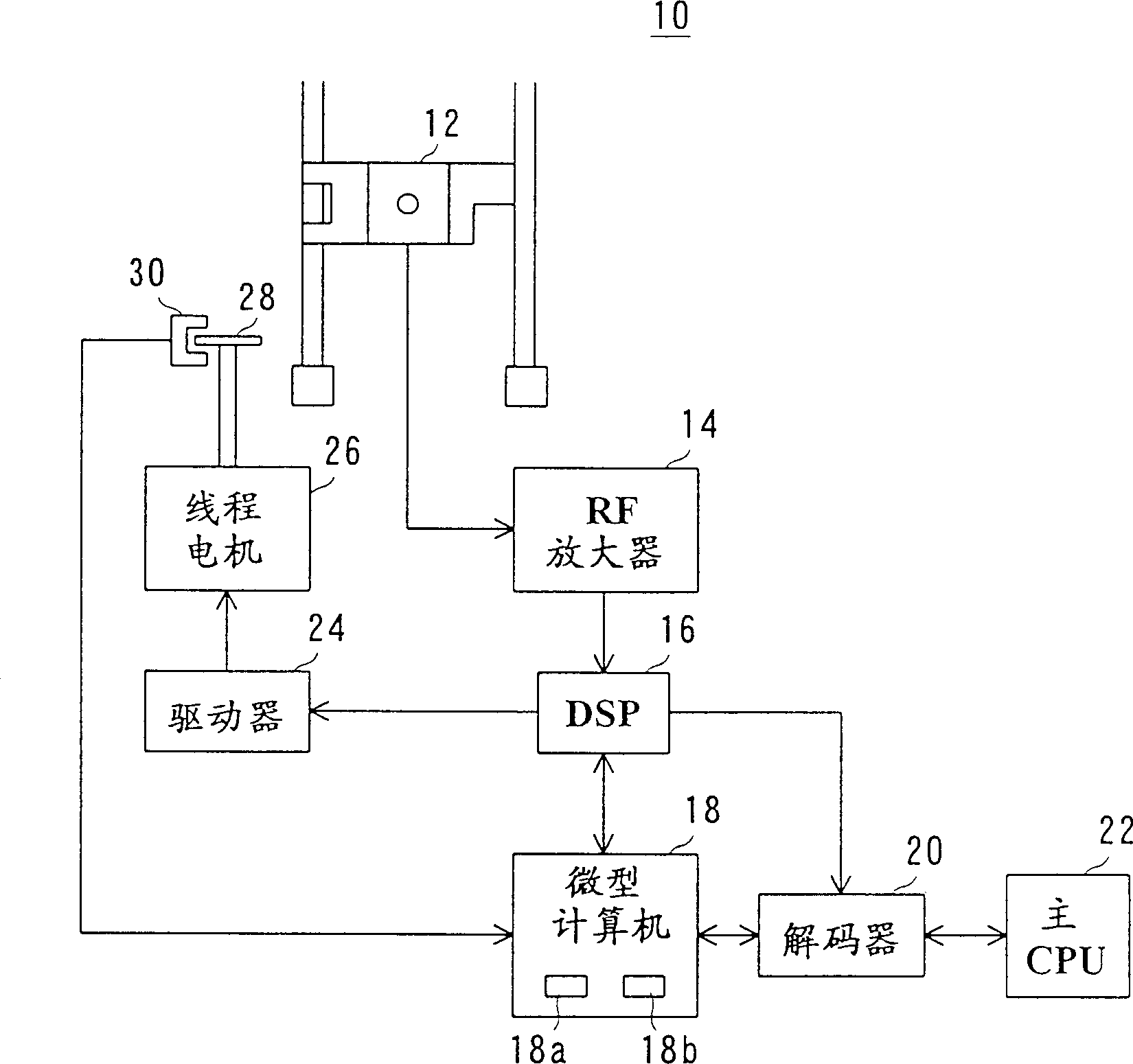
[0016] refer to figure 1 , the disc device 10 includes an optical pickup 12 in this embodiment. The optical pickup 12 reads out the restoration signal and the tracking signal, and sends these two signals to the RF amplifier 14 . The RF amplifier 14 amplifies the restoration signal and the tracking error signal thus read out, and sends the amplified signal to the DSP 16 . The DSP 16 extracts the subcode from the reproduced signal, so that disc information contained in the subcode, such as time information, is sent to the microcomputer 18. On the other hand, the amplified tracking error signal is sent to the microcomputer 18 via the DSP 16 . The microcomputer 18 performs servo control on the pickup 12 based on the disc information and the tracking error signal. In addition, the microcomputer 18 detects the number of skipped tracks from the tracking error signal. The measured number of tracks is counted by a counter 18 a provided in the microcomputer 18 .

[0017] The microc...


PUM


Abstract

A disc apparatus includes a micro-computer. The micro-computer predicts a number of tracks for deceleration from a total number of tracks to be jumped, to thereby calculate a number of tracks for acceleration from the number of tracks for deceleration and the total number of tracks. A thread motor is accelerated until a number of tracks being jumped becomes equal to the number of tracks for acceleration. Thereafter, the thread motor is decelerated to a rotational speed lower than a determined value.

Description

technical field [0001] The present invention relates to a disk device and a thread moving method therefor, and more particularly to a thread moving method and a disk device for making an optical pickup reach a target position at high speed. Background technique [0002] In conventional disk devices of this type, tracks to be skipped are counted based on the current position address and the target position address. Based on the calculated value, the number of acceleration or deceleration is calculated according to a table or calculation equation, so as to accelerate or decelerate the thread motor. [0003] However, in the prior art, the acceleration and deceleration of the thread motor is performed while monitoring the number of tracks. As a result, the thread (pickup) movement speed has not slowed down sufficiently when the data read (on track) operation starts, resulting in irregularities in the tracking process. [0004] On the other hand, a constant voltage is usually a...

Claims


Application Information

Patent Timeline
IPC IPC(8): G11B21/08
CPCG11B21/08
Inventor 桑山康则足立和辉
Owner FUNAI ELECTRIC CO LTD
Why Eureka
Try Eureka