Novel flow velocity detector for water conservancy measurement
A detector and flow velocity technology, which is applied in the field of new flow velocity detectors for water conservancy measurement, can solve the problems of inaccurate data, long response time, and no comparison data.
- Summary
- Abstract
- Description
- Claims
- Application Information
AI Technical Summary
Problems solved by technology
Method used
Image
Examples
Embodiment 1
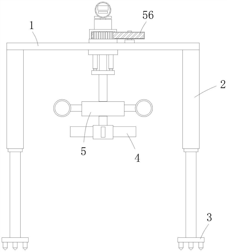
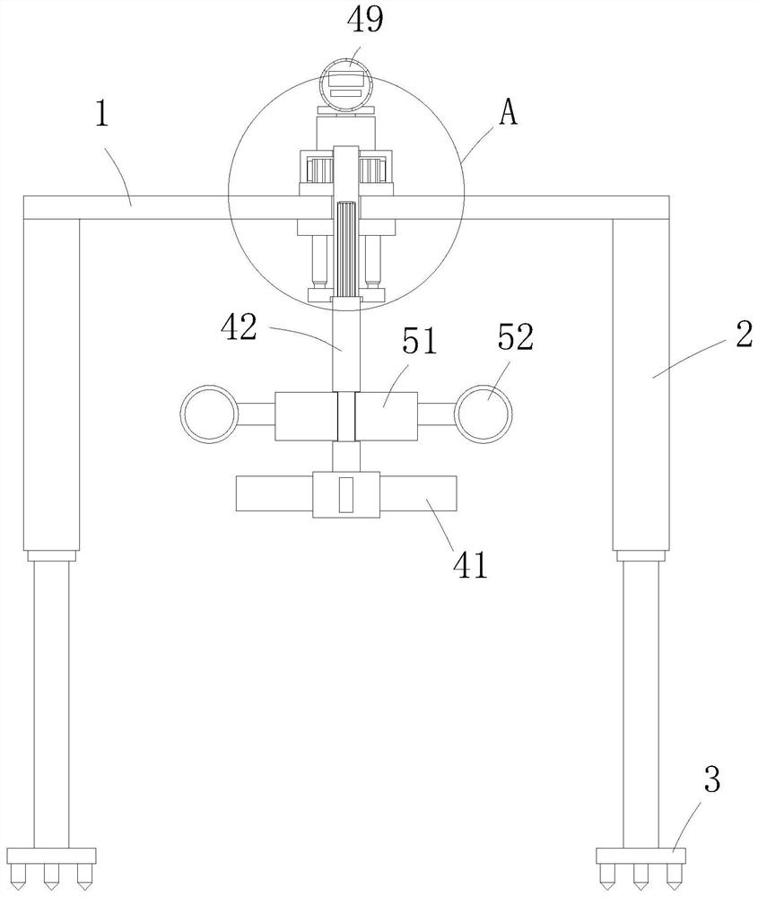
[0035] A new type of flow rate detector for water conservancy measurement, comprising a horizontally arranged frame 1, four electric telescopic legs 2 are fixedly installed on the lower end edge of the frame 1, and fixing nails are fixedly installed on the telescopic ends of the electric telescopic legs 2 Plate 3 is used to extend the electric telescopic legs 2 downward when the detector enters the water, and locate the fixed nail plate 3 on the bottom of the water, so as to realize accurate measurement. The lower end of the frame 1 is provided with a flow velocity measurement mechanism 4 and a flow velocity correction mechanism 5 The flow velocity measuring mechanism 4 is used to measure the water flow velocity in the river channel or the canal, and the flow velocity correction mechanism 5 is used to assist measurement and give data, and to calibrate in combination with the flow velocity of the flow velocity measuring mechanism 4, so as to ensure accurate measurement;
[0036]...
Embodiment 2
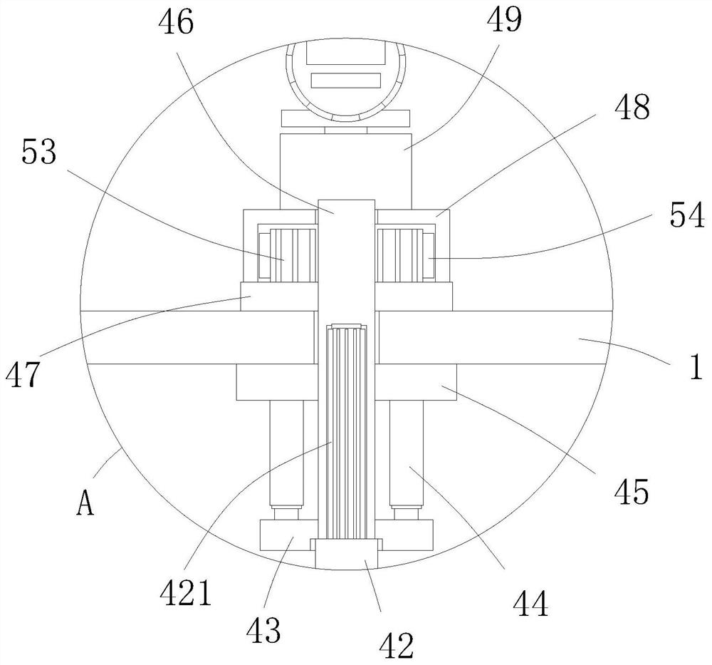
[0043] The difference between this embodiment and embodiment 1 is that, as image 3 As shown, the upper end of the drive shaft 42 is covered with a lifting plate 43, and the upper edge of the lifting plate 43 is connected with the lower plate 45 through a plurality of oil cylinders 44, through the synchronous start and stop of a plurality of oil cylinders 44, the liquid level adjustment can be realized. The detection of water flow velocity at different liquid levels can meet the needs of water conservancy measurement.
[0044] In this example, if image 3 As shown, a plurality of the oil cylinders 44 are distributed in an annular array, and the number of the oil cylinders 44 is more than or equal to three, effectively ensuring the movement of the rotating impeller 41 and the plastic moving block 51. At the same time, the annular arrangement of the oil cylinders 44 can effectively Ensure the positioning of the drive shaft 42 and the sleeve shaft 46, and the protection device w...
PUM
 Abstract
Description
Claims
Application Information
 - Generate Ideas
- Intellectual Property
- Life Sciences
- Materials
- Tech Scout
- Unparalleled Data Quality
- Higher Quality Content
- 60% Fewer Hallucinations
Browse by: Latest US Patents, China's latest patents, Technical Efficacy Thesaurus, Application Domain, Technology Topic, Popular Technical Reports.
© 2025 PatSnap. All rights reserved.Legal|Privacy policy|Modern Slavery Act Transparency Statement|Sitemap|About US| Contact US: help@patsnap.com


