Method for making construction material two-side surface light extraction and LED surface light source for lighting

A building decoration material, LED surface light source technology, applied in the direction of plane light source, electroluminescence light source, light source, etc., can solve the problems of single light source, high cost, poor decorative effect, etc., to achieve colorful pictures, enhance transparency, maintain aesthetic effect

Inactive Publication Date: 2008-01-16
CREE SHANGHAI OPTO DEV LTD
View PDF2 Cites 6 Cited by
  • Summary
  • Abstract
  • Description
  • Claims
  • Application Information

AI Technical Summary

Problems solved by technology

[0009] The structure is simple and easy to operate, but the decorative effect is not good, especially during the day when the wires hang outside the building, which has a great impact on the overall appearance of the building
[0010] 2. Gradient wall panels or wall strips with LEDs as backlights have large thickness, low transparency, complicated drive control, and relatively high cost;
[0013] This has the following disadvantages: the decorative pattern cannot be displayed, only a single light source; the optical cooperation between LED and glass is difficult, and every time it is used, it is necessary to make corresponding optical design for glass and LED to meet the optical requirements , which brings trouble to the application; in addition, due to the attenuation of the LED light source, the size of the surface light source is subject to certain restrictions, and the light uniformity is also subject to certain restrictions
[0018] 1. The electrode pins are metal or alloy wires. As the number of LED components used increases, a dense and complex metal wire network will inevitably be formed on the glass curtain wall, which will affect the transparency and external aesthetics of the glass curtain wall to be decorated;
[0019] 2. For occasions that require different luminous characteristics, the wiring structure is too complicated and the process is quite difficult, resulting in relatively high costs. For large-area glass curtain walls, it is difficult to connect wires between modules, so in actual engineering There are bound to be many constraints in the application
[0020] In addition, due to the unidirectionality of light emitted by LED light source devices, the light sources of the above-mentioned technical solutions can only emit light from one side. If it is used as lighting for large buildings such as curtain walls, observers cannot see the effect of the light source on both sides of the light source at the same time.

Method used


Image

  • Method for making construction material two-side surface light extraction and LED surface light source for lighting
  • Method for making construction material two-side surface light extraction and LED surface light source for lighting
  • Method for making construction material two-side surface light extraction and LED surface light source for lighting

Examples


Embodiment 1

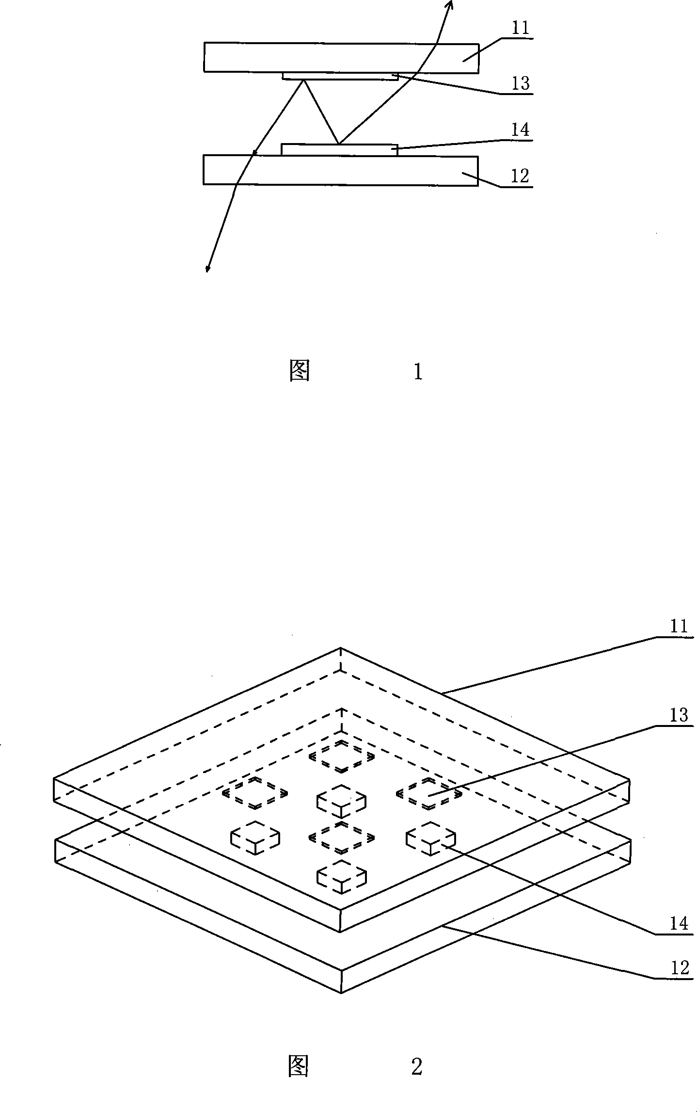
[0052] The structure of using an optical thin film to realize double-sided light emission on the upper substrate is shown in Fig. 2 .

[0053] In Fig. 2, according to the installation position of the LED point light source 14 on the lower transparent substrate 12, a reflective film 13 is coated on the corresponding position of the upper transparent substrate 12, and a part of the light emitted by the LED is reflected back to the lower transparent substrate 12 when encountering the reflective film. , to emit light in the lower substrate; and another part of the light emitted by the LED, when it encounters a place without a reflective film, is directly transmitted from the upper transparent substrate, thereby achieving the effect of double-sided light emission.

Embodiment 2

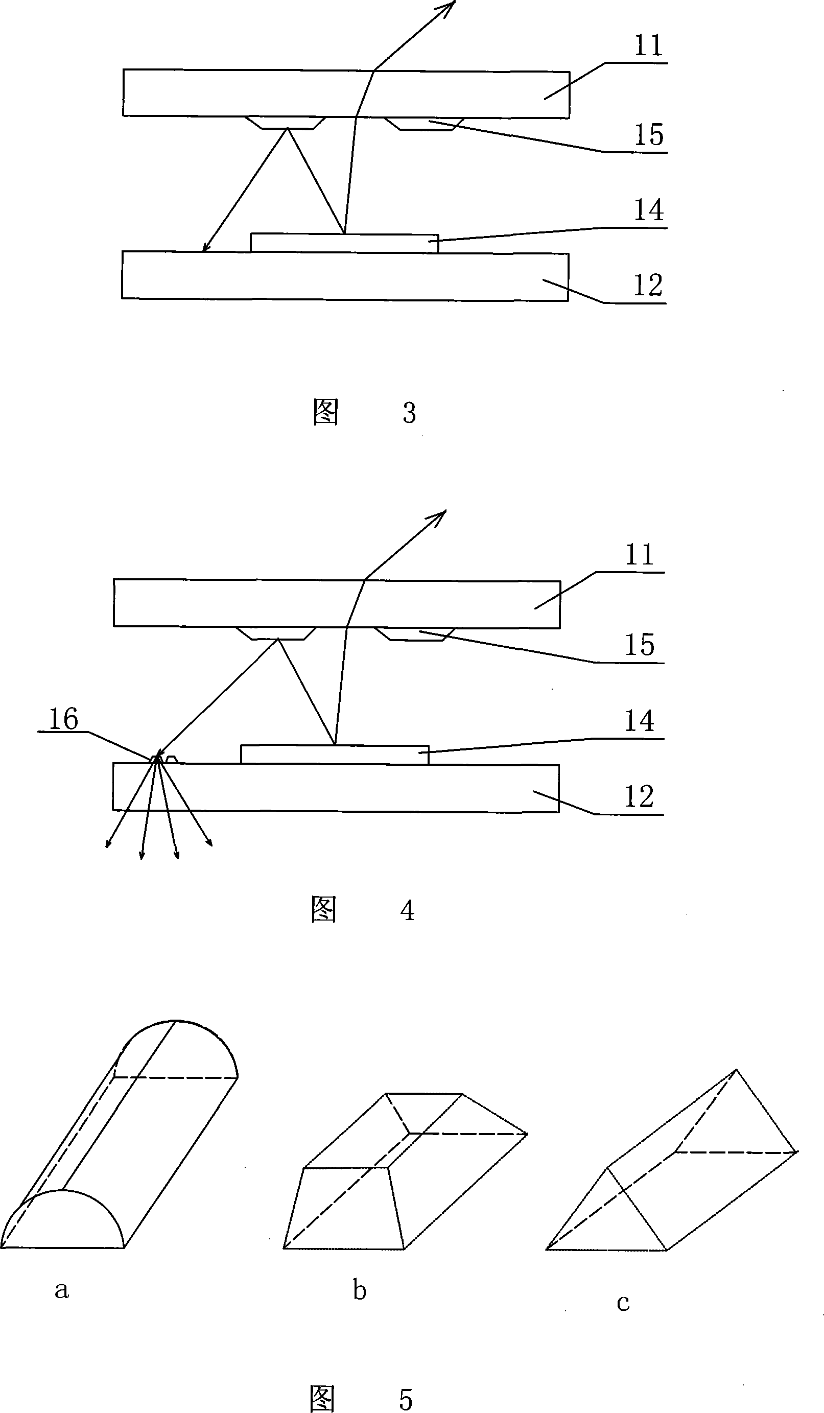
[0055] The structure of the upper substrate using a reflective / diffusing structure to realize double-sided light output is shown in Figure 3 .

[0056] In Fig. 3, several inverted trapezoidal reflective structures 15 are etched on the upper transparent substrate 11 corresponding to the position of the LED point light source 14, and a certain gap is left between each inverted trapezoidal structure; The inverted trapezoidal reflective structure reflects back to the lower transparent substrate 12 to achieve the effect of double-sided light emission.

[0057] In this solution, by changing the geometric dimensions such as the angle of the inverted trapezoid, the direction of light reflection can be adjusted, so that most of the reflected LED light is emitted from the lower transparent substrate, so that the double-sided light emission effect of the light source is better.

Embodiment 3

[0059] Both the upper and lower substrates adopt optical reflective / diffusion structures to realize double-sided light emitting structures, as shown in FIG. 4 .

[0060] In Fig. 4, in order to enhance the light extraction rate of the lower transparent substrate, a certain pattern is etched on the lower transparent substrate or a light-enhancing film 16 is coated to increase the light intensity of the lower transparent substrate and reduce the difference in light intensity between the upper and lower transparent substrates. It helps to achieve the uniformity of double-sided light output.


PUM


Abstract

The invention provides a method for making both sides of architectural decoration material lighting and lighting-used LED surface light source thereof, belonging to building construction filed. The invention is characterized in that an upper transparent substrate and a lower transparent substrate are equipped, an LED point light source is positioned between the upper and the lower transparent substrates, and an optical membrane is coated on or an optical reflecting and / or diffusing structure is etched on part of the upper and / or lower transparent substrates. By changing the optical structure of part of the transparent substrates, the light emitted from the LED light source is partially emerged from the upper transparent substrate, while the other part of light is emerged from the lower transparent substrate. The invention changes the optical structure of the transparent substrates, so that observer can observe light simultaneously emerged from the upper and the lower sides of the light source. Meanwhile, the invention adopts transparent conductive coating and direct illumination of LED, so as to improve the transparency of the building to be decorated and meet the large-size lighting requirements. The invention can be widely used in various types of glass curtain walls of buildings or architectural decoration materials.

Description

technical field [0001] The invention belongs to the field of general building construction, and in particular relates to a glass curtain wall which adopts LED as a light source and can be applied to buildings to realize photoelectric lighting decoration. Background technique [0002] LED (Light Emitting Diode) is a light-emitting diode, which is composed of a PN layer and a light-emitting layer in it. With different materials of the light-emitting layer, its light-emitting color is different. [0003] Since the emergence of nitride LEDs in the early 1990s, the luminous efficiency of LEDs has made a qualitative leap. Then the successful development of blue LED made white LED possible. The successful development of the physical and chemical process and process technology of white light LED provides a reliable guarantee for the realization of various color LED light source products. [0004] In recent years, the high-power LED manufacturing process and the successful resoluti...

Claims


Application Information

Patent Timeline
Patent Type & Authority Applications(China)
IPC IPC(8): F21V19/00H05B33/10F21W121/00F21Y101/02F21Y105/00F21Y115/10
CPCB32B17/10036B32B17/10541
Inventor 施毓灿
Owner CREE SHANGHAI OPTO DEV LTD
Why Eureka
Try Eureka