
Frame data creation method and device, frame data creation program, and plotting method and device

A technology for generating devices and generating programs, which is applied in printing devices, printing, electrical components, etc., can solve the problems of time-consuming and frame data time-consuming, and achieve the effects of high-speed frame data, high-speed readout, and high-speed generation

Inactive Publication Date: 2008-01-09
FUJIFILM CORP
View PDF1 Cites 4 Cited by
  • Summary
  • Abstract
  • Description
  • Claims
  • Application Information

AI Technical Summary

Problems solved by technology

[0008] However, as shown in FIG. 18, since the above-mentioned image data 1 has pixel data 5 arranged two-dimensionally in the sub-scanning direction corresponding to the scanning direction of the DMD and in the main scanning direction orthogonal to the sub-scanning direction, for example, In the case of generating the frame data in the exposure device in which the DMD is inclined at a predetermined angle with respect to the scanning direction as described above, the pixel data corresponding to each micromirror is sequentially read, for example, the pixel data arranged along the main scanning direction in FIG. 18 In the case of storing in the above-mentioned memory in the direction where the addresses are continuous, the addresses of the pixel data corresponding to each micromirror are stored discretely in the address space of the memory viewed from the control mechanism controlling the memory. Addresses are accessed one by one, and the operation of reading pixel data is very time-consuming in memory control, and it is very time-consuming to obtain all frame data

Method used


Image

  • Frame data creation method and device, frame data creation program, and plotting method and device
  • Frame data creation method and device, frame data creation program, and plotting method and device
  • Frame data creation method and device, frame data creation program, and plotting method and device

Examples


Embodiment Construction

[0055] Hereinafter, the frame data generating method and device, program, rendering method, and exposure device using the device according to one embodiment of the present invention will be described in detail with reference to the drawings.

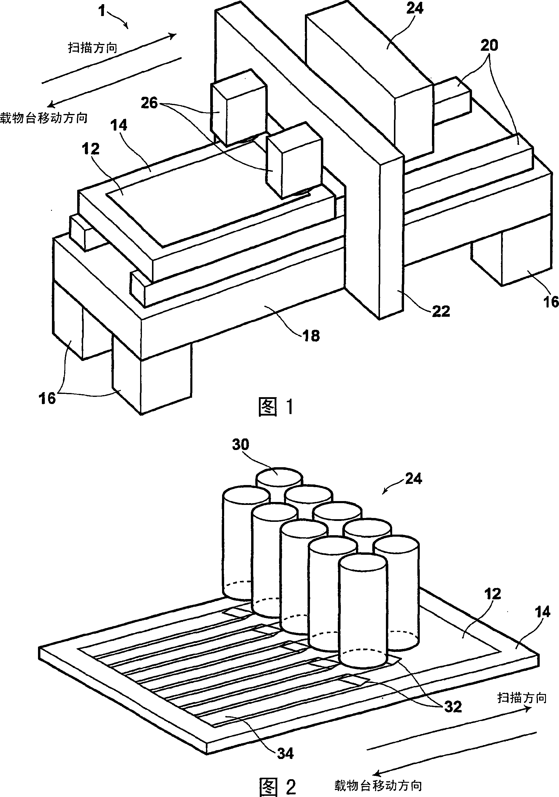
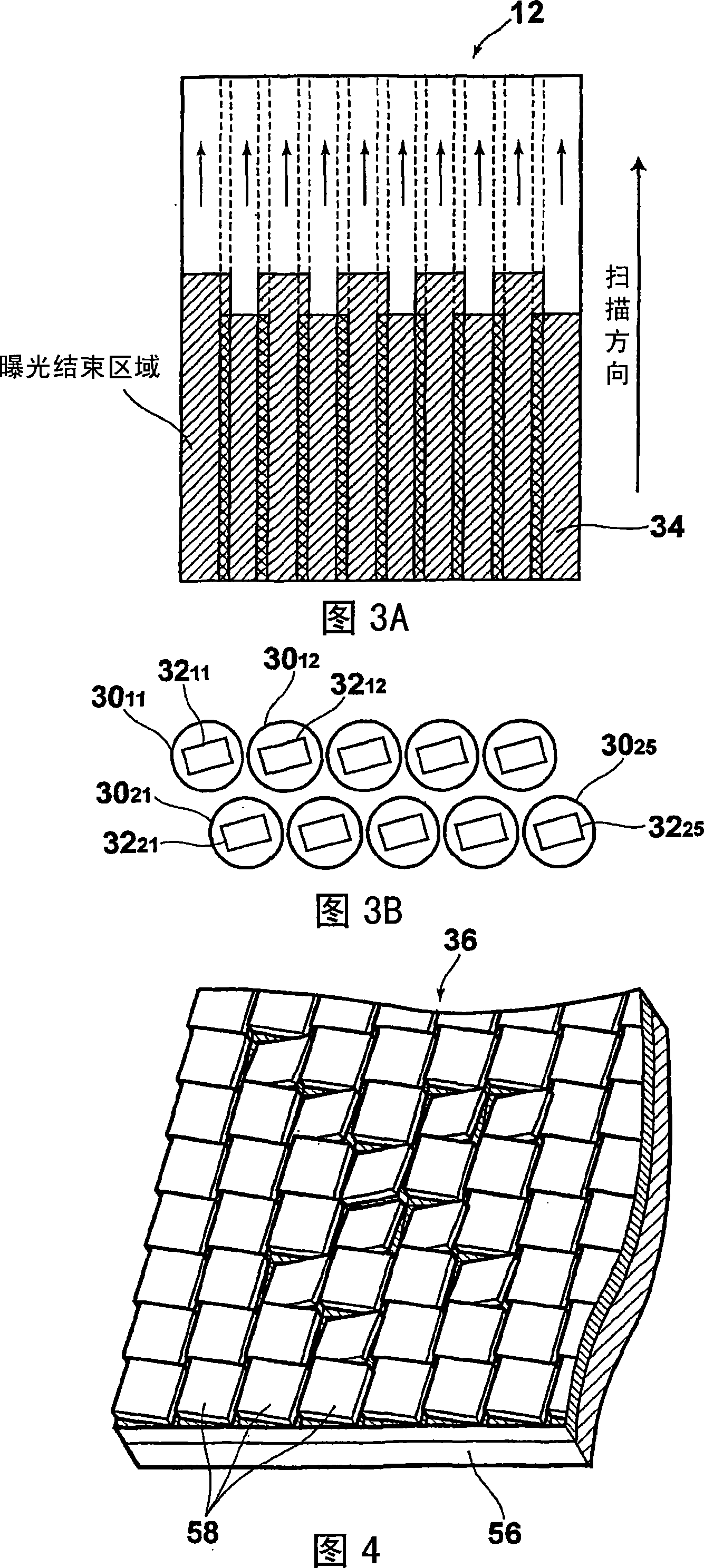
[0056] This exposure device is an exposure device using a DMD as a drawing dot forming unit in the present invention, and is characterized by a method of generating frame data input to the DMD. First, the overall configuration of the exposure device according to this embodiment will be described. FIG. 1 is a perspective view showing a schematic configuration of an exposure apparatus according to the present embodiment.

[0057] As shown in FIG. 1, the exposure apparatus 10 of this embodiment is provided with the flat plate-shaped movable stage 14 which adsorb|sucks and holds the photosensitive material 12 on the surface. Furthermore, two guide rails 20 extending in the moving direction of the stage are provided on the upper surface of a ...


PUM


Abstract

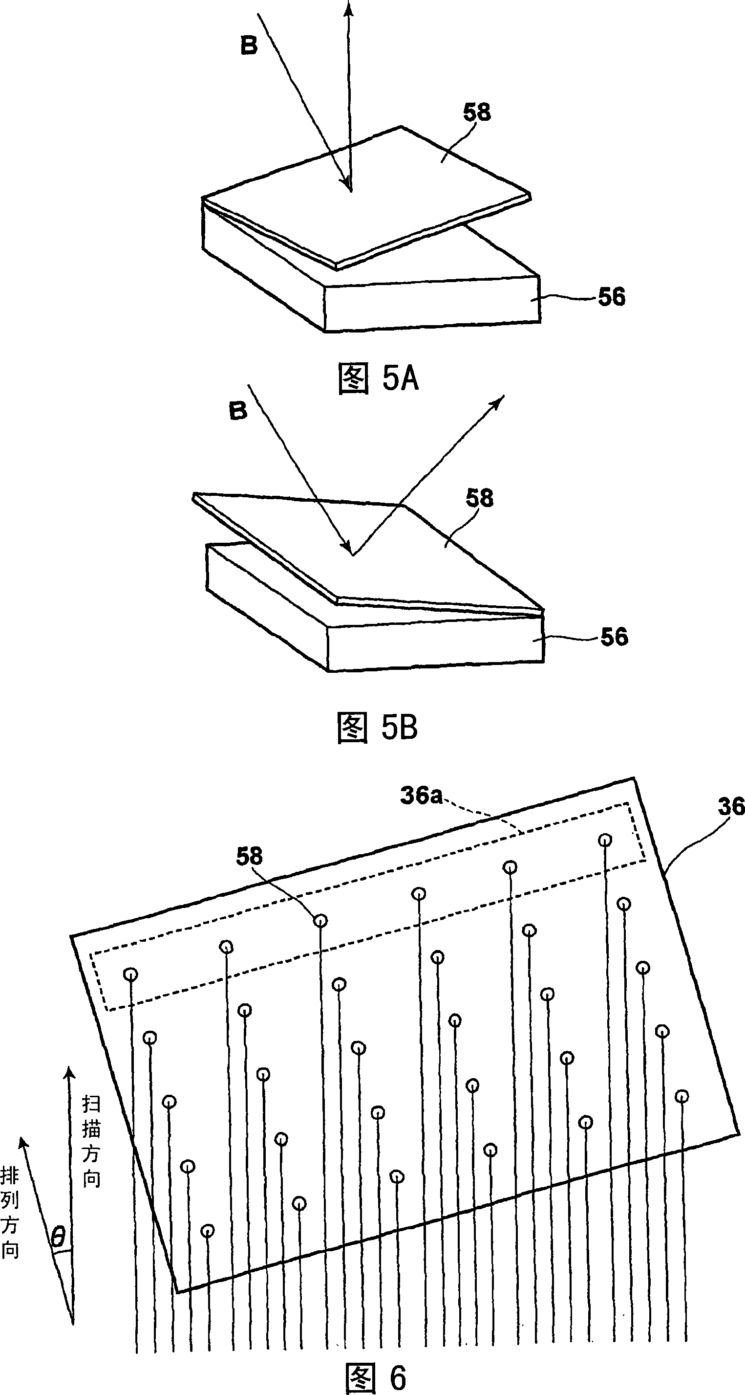
It is possible to rapidly create frame data used when moving a spatial light modulation element in a scan direction and forming an image by inputting the frame data into a spatial light modulation element in accordance with the movement in the scan direction. There is provided a method for creating the frame data used when moving the spatial light modulation element having a plurality of arranged plotting element groups in the scan direction defining an inclination angle against the arrangement direction of the plotting element groups and inputting the frame data into the spatial light modulation element to form an image in accordance with the movement. The frame data creation method creates frame data according to image data in which pixel data are two-dimensionally arranged in a sub-scan direction corresponding to the aforementioned scan direction and a main scan direction orthogonal to the sub-scan direction. The image data is subjected to deformation processing sot that the image data corresponding to the plotting element groups (circle 1 to circle 6) are arranged in the main scan direction and the frame data is created in accordance with the deformed image data.

Description

technical field [0001] The present invention relates to a frame data generating method, device and program for generating frame data used when forming an image by relatively moving a drawing point forming part such as a spatial light modulation element in a predetermined scanning direction with respect to a drawing surface, and related to the use of the frame A data generating method and device, and a rendering method and device for rendering using frame data generated and obtained by a program. Background technique [0002] Conventionally, various drawing devices are known that form a desired two-dimensional pattern represented by image data on a drawing surface. [0003] As such a drawing apparatus, for example, various exposure apparatuses have been proposed that use spatial light modulation elements such as digital micromirror devices (hereinafter referred to as DMDs) to modulate light beams according to image data and perform exposure. The DMD is configured by arrangin...

Claims


Application Information

Patent Timeline
Patent Type & Authority Applications(China)
IPC IPC(8): B41J2/46B41J5/30B41J21/00H04N1/23
CPCH04N1/047H04N1/195H04N1/1008H04N2201/04767B41J2/46B41J5/30B41J21/00H04N1/23
Inventor 中谷大辅城后尚纯植村隆之山本千季
Owner FUJIFILM CORP
Learn More