
Intelligent antenna implementing method and apparatus under DTX or HSDPA mode

A technology of smart antenna and implementation method, applied in diversity/multi-antenna system, space transmit diversity, error prevention/detection through diversity reception, etc., can solve the problem of difficult to reflect the performance of smart antenna, angle of arrival or beamforming weight Difficult to apply to downlink, system robustness degradation, etc.

Active Publication Date: 2008-01-02
GLOBAL INNOVATION AGGREGATORS LLC
View PDF1 Cites 15 Cited by
  • Summary
  • Abstract
  • Description
  • Claims
  • Application Information

AI Technical Summary

Problems solved by technology

For DTX or HSDPA mode, the time interval between the uplink and downlink of a certain user may be relatively large. When the wireless channel environment is complex or the user moves tangentially at a fast speed, the angle of arrival or beamforming estimated by the uplink The weight value may be difficult to apply to the downlink, which directly affects the system performance of the smart antenna, resulting in a decrease in the robustness of the system
[0004] The basic principle of the Chinese invention patent application "downlink beamforming method and device for wireless channels" (application number: 20041000360.5, publication number: CN1658526A, publication date: August 24, 2005) is to use the angle of arrival and the maximum gain of received power Or the change of beam width optimizes the shaped beam or selects a shaped beam from multi-level beams, which is used to compensate the influence of the complexity of the channel environment to a certain extent, but the real-time adaptability of this method to wireless channel changes And the degree of improvement to the system performance is relatively limited, especially in the uplink DTX mode or HSDPA mode, it is difficult to reflect the performance of the smart antenna

Method used


Image

  • Intelligent antenna implementing method and apparatus under DTX or HSDPA mode
  • Intelligent antenna implementing method and apparatus under DTX or HSDPA mode
  • Intelligent antenna implementing method and apparatus under DTX or HSDPA mode

Examples


Embodiment Construction

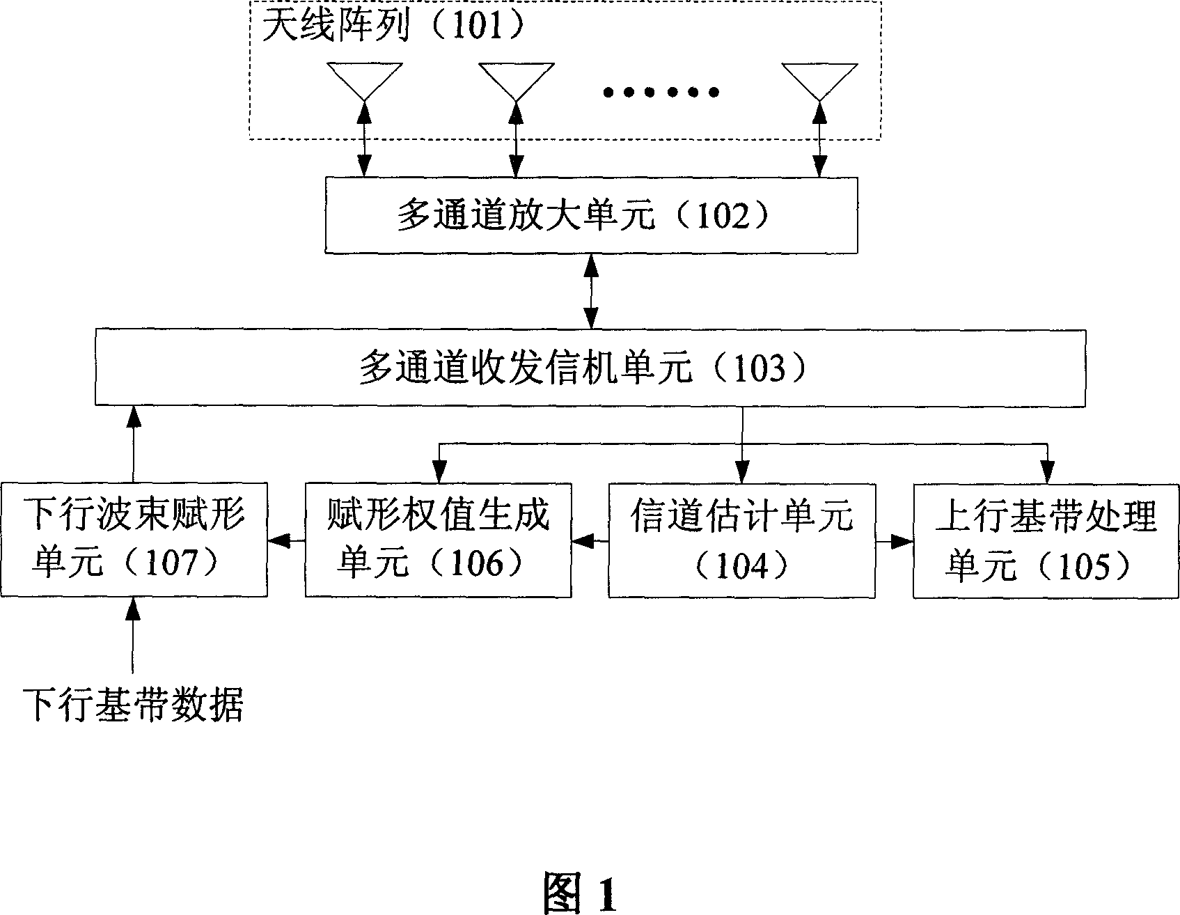
[0052] As shown in Figure 1, the smart antenna realization device of the CDMA communication system of a preferred embodiment of the present invention under DTX or HSDPA mode comprises:

[0053] 1) Antenna array (101)

[0054] 2) Multi-channel amplification unit (102)

[0055] 3) Multi-channel transceiver unit (103)

[0056] 4) channel estimation unit (104)

[0057] 5) Uplink baseband processing unit (105)

[0058] 6) Shaped weight generation unit (106)

[0059] 7) Downlink beamforming unit (107)

[0060] For the uplink, the multi-channel amplifying unit (102) works in a low-noise amplifying mode, and the wireless signal is received by the antenna array (101), amplified by the multi-channel amplifying unit (102), and then transmitted to the multi-channel transceiver unit (103 ); the multi-channel transceiver unit (103) converts the radio frequency signal into a digital baseband signal after filtering, down-conversion, analog-to-digital conversion, etc.; the multi-channel t...


PUM


Abstract

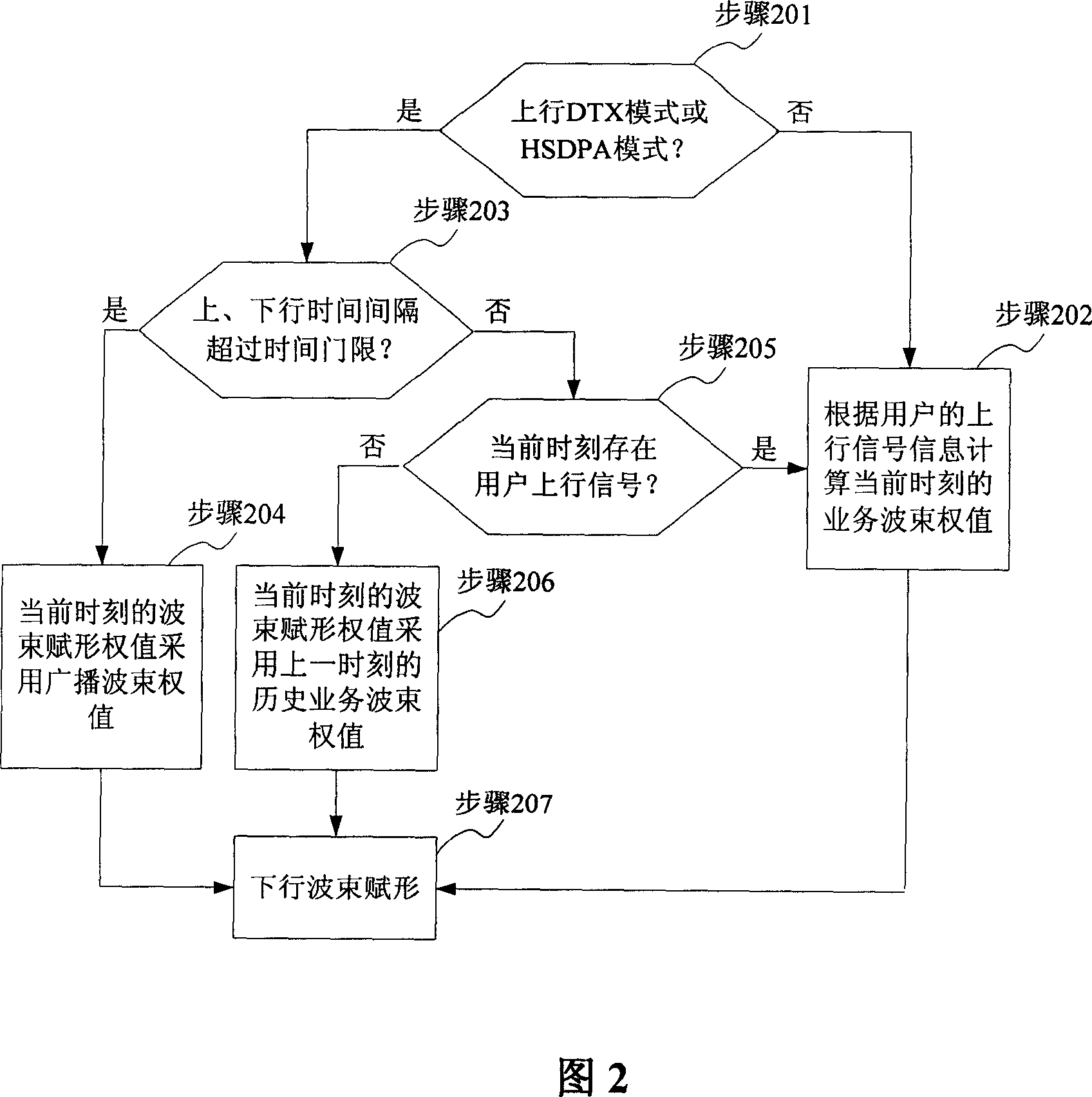
The invention relates to an intelligent antenna under DTX or HSDPA mode, and a relative device, wherein the method comprises that (1), judging if the system setting is ascending DTX or HSDPA mode, (2), according to user ascending signal information, calculating out beam shaping weighting value of current user special channel, (3), judging if the distance between ascending and descending time is over a time threshold value, (4), current beam shaping weighting value uses the beam shaping weighting value of public channel, (5), judging if current time has user ascending signal, (6), the current beam shaping weighting value uses the history service beam weighting value of last time, (7), according to the beam shaping weighting value, realizing descending beam shaping. The invention can effectively adapt the real0-time change of wireless channel, improve the intelligent antenna property of ascending DTX or HSDPA mode, and improve system stability and reliability.

Description

technical field [0001] The present invention relates to a kind of Code-Division Multiple Access (Code-Division Multipl Access) (hereinafter referred to as CDMA) communication system in Discontinuous Transmission (Discontinuous Transmit) (hereinafter referred to as DTX) or High Speed ​​Downlink Packet Access (High Speed ​​Downlink Package Access) ) (hereinafter referred to as HSDPA) mode smart antenna implementation method and device, in particular related to synchronous code division multiple access (Synchronous Code Division Multiple Access) (hereinafter referred to as SCDMA) communication system in the uplink DTX mode or the beamforming method under the HSDPA mode and devices. Background technique [0002] Smart antennas use the spatial characteristics of signal transmission and digital signal processing technology to achieve beamforming in specific angular directions, thereby reducing noise interference, increasing capacity, expanding coverage, improving communication qua...

Claims


Application Information

Patent Timeline
IPC IPC(8): H04B7/02H04B7/08H04L5/14H04L1/02
Inventor 秦洪峰曾召华史凡李斌
Owner GLOBAL INNOVATION AGGREGATORS LLC
Learn More