Forming method of current divider

A technology of shunts and resistors, applied in the field of shunts, can solve the problems of low degree of mechanization and automation, high requirements for metal connection, large equipment investment, etc., and achieve saving of material resources and foreign exchange, high and smooth weld quality, and flexible structural design Effect

Inactive Publication Date: 2008-01-02
TONGXIANG WEIDA ELECTRONICS
View PDF1 Cites 20 Cited by
  • Summary
  • Abstract
  • Description
  • Claims
  • Application Information

AI Technical Summary

Problems solved by technology

[0002] There are various forms of current shunts, which are composed of a single metal material. This kind of shunt is easy to manufacture and the manufacturing process is simple; there are also shunts made of multiple metal sheets connected, and the most common form is the surface of the metal sheet. The large-area connection between different metals has a large contact surface, and the welding process is also simple to operate. This kind of shunt generally uses the process of punching metal sheets, welding, and shaping, but now a new type of shunt has appeared. As disclosed in the patent 200630108721.0 of the electronic energy meter shunt, the connection between different metals of the shunt is the connection between the side end surface of the metal material and the side end surface. This type of shunt uses the most economical materials, but it is different The requirements for the metal connection of properties are high, especially the side-end connection between different metals. However, due to the different physical properties of the metals, the contact area between the side-end surfaces is small, so that the products welded by ordinary welding methods cannot meet the requirements of the shunt. required requirements
For example, brazing needs to add solder and overall heating, and the product is easy to deform, which affects the performance of the product; plasma arc welding and argon arc welding need to add solder and use electrodes, which also affects the performance of the product; resistance welding requires Adding solder and using electrodes will lead to large thermal deformation; low degree of mechanization and automation; the first few welding methods are difficult to control product quality; electron beam welding needs to be welded in a vacuum state, which has low production efficiency and large equipment investment; laser welding is generally considered Cannot be used for welding of this type of shunt
The existence of this problem has brought great technical obstacles to the manufacture of new shunts

Method used


Image

  • Forming method of current divider

Examples


Embodiment Construction

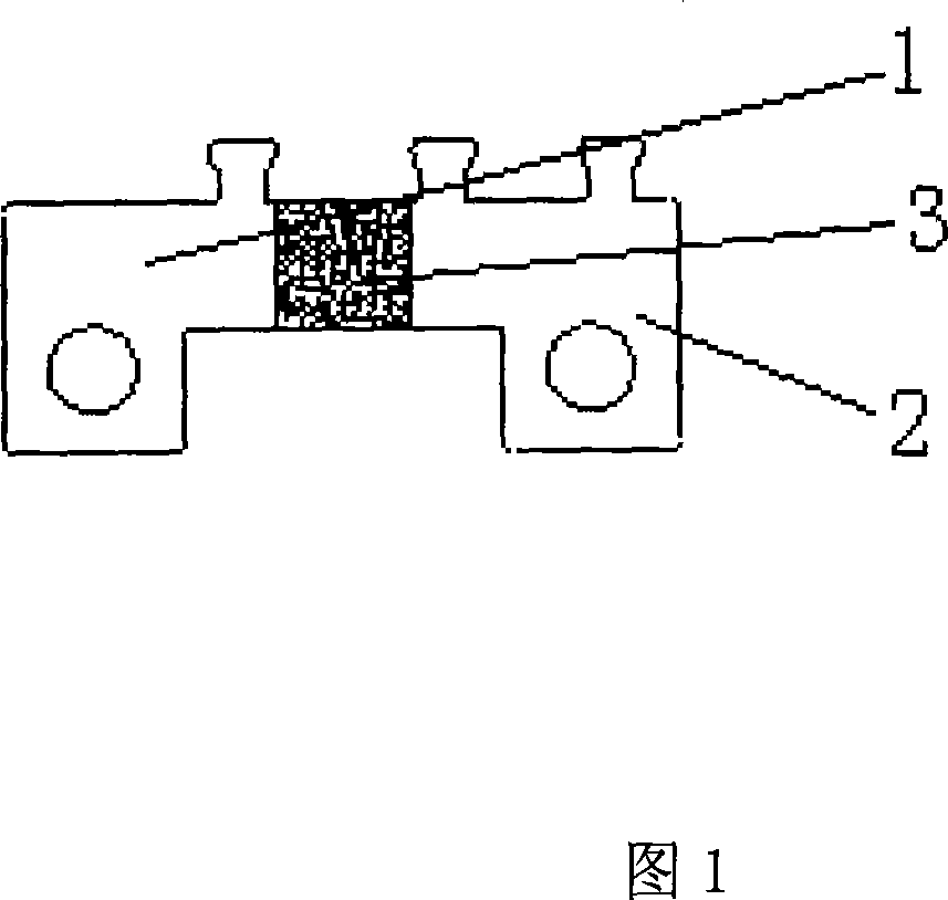
[0010] In Fig. 1, the shunt of the present invention is composed of two pieces of red copper 1 and 2 and a piece of manganese copper 3, and the opposite side end faces of the manganin sheet 3 are respectively connected with the side end faces of the two pieces of red copper 1 and 2 , the connection is welding, and there are fixed holes and sampling ends on the copper sheets 1 and 2. The specific forming method is as follows 1. Manganese copper sheet 1, 2 and manganese copper sheet 3 are made. Two 1mm thick red copper sheets 1 and 2 are punched into a rectangle. The length is 1000mm and punched into one piece; first put the above-mentioned copper sheet 1 and a piece of manganese-copper sheet 3 into a high-power laser welding machine for welding, and pass nitrogen gas during welding to prevent the oxidation of the copper sheets 1 and 2 and the manganese-copper sheet being welded. In the same way, the other side of the copper sheet 2 and the manganese-copper sheet 3 is welded; th...


PUM


Abstract

The invention discloses a forming method of diverter used in electric energy meter, specially a forming method of diverter made by resistance metal material and conducting metal material. The purpose of the invention is providing a forming method of diverter whose operation is easy, performance is stable, and efficiency is high. The method includes three steps of selecting material, welding and punching figuration. The forming method of diverter possesses characters that course of production is unpolluted, precision is high.

Description

technical field [0001] The invention relates to a shunt used on an electric energy meter, in particular to a method for forming a shunt composed of a resistance metal material and a conductive metal material. Background technique [0002] There are various forms of current shunts, which are composed of a single metal material. This kind of shunt is easy to manufacture and the manufacturing process is simple; there are also shunts made of multiple metal sheets connected, and the most common form is the surface of the metal sheet. The large-area connection between different metals has a large contact surface, and the welding process is also simple to operate. This kind of shunt generally uses the process of punching metal sheets, welding, and shaping, but now a new type of shunt has appeared. As disclosed in the patent 200630108721.0 of the electronic energy meter shunt, the connection between different metals of the shunt is the connection between the side end surface of the ...

Claims


Application Information

Patent Timeline
Patent Type & Authority Applications(China)
IPC IPC(8): G01R11/02
Inventor 朱永虎
Owner TONGXIANG WEIDA ELECTRONICS
Why Eureka
Try Eureka